 |  |
| |
|  |
 diagram from Olson 1976 |  #48936 from AT&T Archives |
 diagram from Olson 1977 |  from NMAH |  from "Dawn of Sound" exhibit |
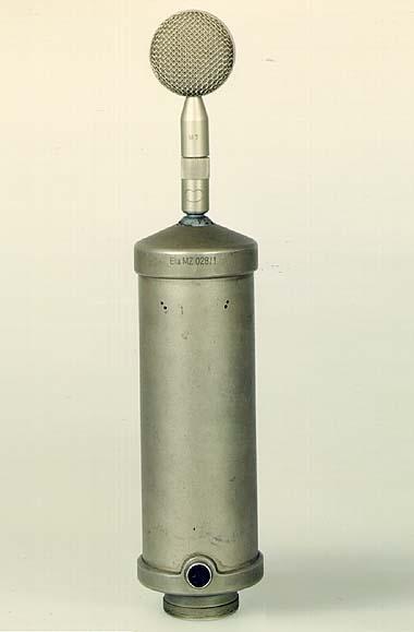 from Neumann History | 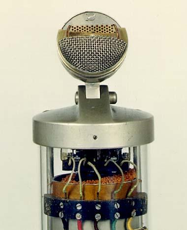 from Neumann History | 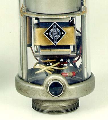 from Neumann History |
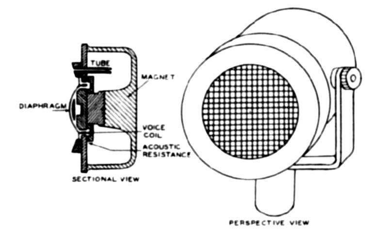 diagram from Olson 1977 |  from Fagen 1975 |  diagram from Olson 1977 |
 diagram from Olson 1977 |  from Judy McDonald |
 diagram from Olson 1977 | 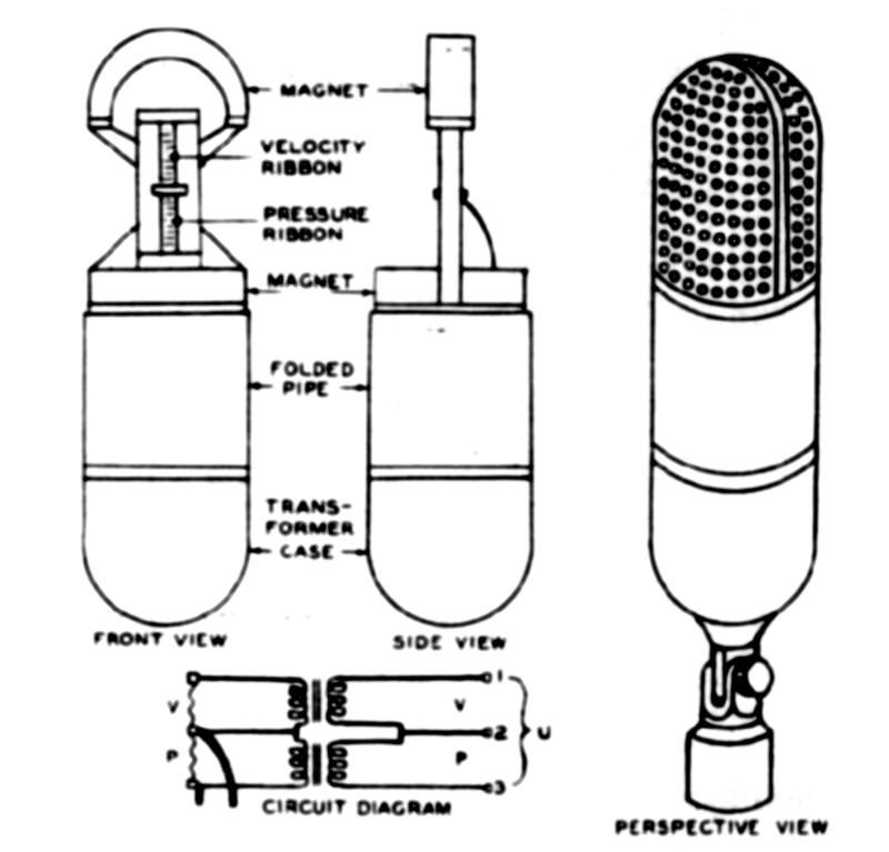 diagram from Olson 1976 |
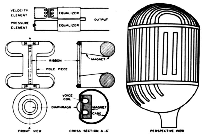 diagram from Olson 1976 | 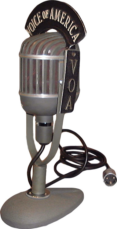 from NMAH |
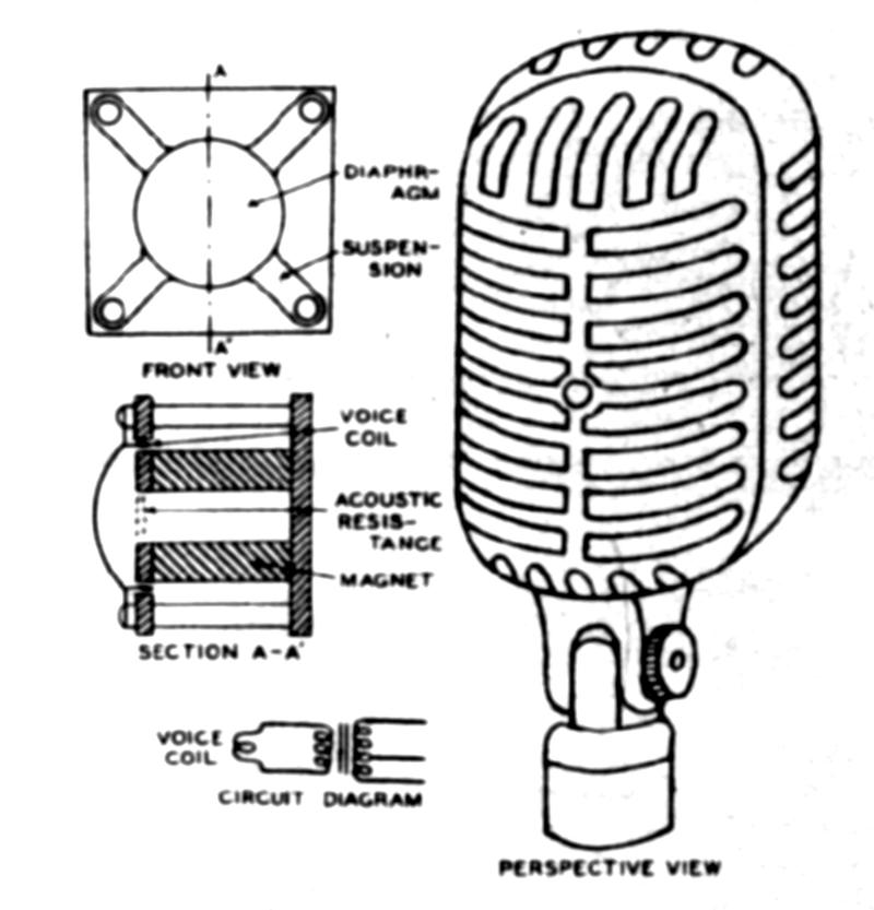 diagram from Olson 1977 |  diagram from Olson 1976 |
 |  |
 |  |