Magnetic Recording Equipment


The following description was written by Semi J. Begun who pioneered magnetic tape recording at the Brush Development Company in Cleveland, Ohio. Begun immigrated from Germany in 1938 where he had developed a steel-tape recorder for the C. Lorenz Company. In 1939, he led the research program at Brush Development that produced recording equipment for the U. S. military in World War II. This is Chapter 6 of the book he wrote in 1949 on magnetic recording, including the original illustrations. In Chapter 1 he described the history of magnetic recording.


page 135

Chapter 6

Magnetic Recording Equipment

Years of patient research have resulted in the development of magneticrecording instruments vastly superior to the first crude embodiments of Poutsen's discovery. The pressure of World War II stimulated this development much beyond anything that could reasonably have been expected to take place in a corresponding era of peace. As a result of this, magnetic-recording equipment, for the first time in its fifty-year history, is at last available to the man on the street.

An old saw contends that "the proof of the pudding is in the eating." Some of the pudding, at least, is now ready to be eaten. Whether the man on the street will like the flavor remains to be seen. Also, it must be kept in mind that not all the pudding is cooked; many more organizations are considering entering the field. Five years hence everyone will be in a much better position to evaluate the situation than is possible now.

Five years, or five hundred years, for that matter, will not see the end of progress. This chapter, in which it is proposed to discuss some of the historically important instruments and the instruments that are available today, must therefore be continually subject to revision, possibly radical revision. Tomorrow may see advances more significant than all that has gone before.

WIRE RECORDERS

Telegraphone

THE TELEGRAPHONE. The first magnetic recorder to be made commercially available anywhere was the Telegraphone, manufactured by the American Telegraphone Company, Springfield, Massachusetts, and shown in Fig. 6-i. This instrument, which was designed primarily as a dictating machine, used 0.01-inch carbon-steel wire as the recording medium, and this wire was propelled by a nonconstant-speed drive with a minimum velocity of about 7 feet per sec. The same motor could be connected to the supply or take-up reel through magnetically operated friction clutches. A "feeler" riding against the wire indicated the elapsed time and automatically stopped the mechanism when the wire had built up to a predetermined diameter on one or the other reel. Rewind speed was only slightly faster than recording-reproducing speed. A carbon microphone coupled directly to the recording head supplied the recording current. For reproduction,

page 136

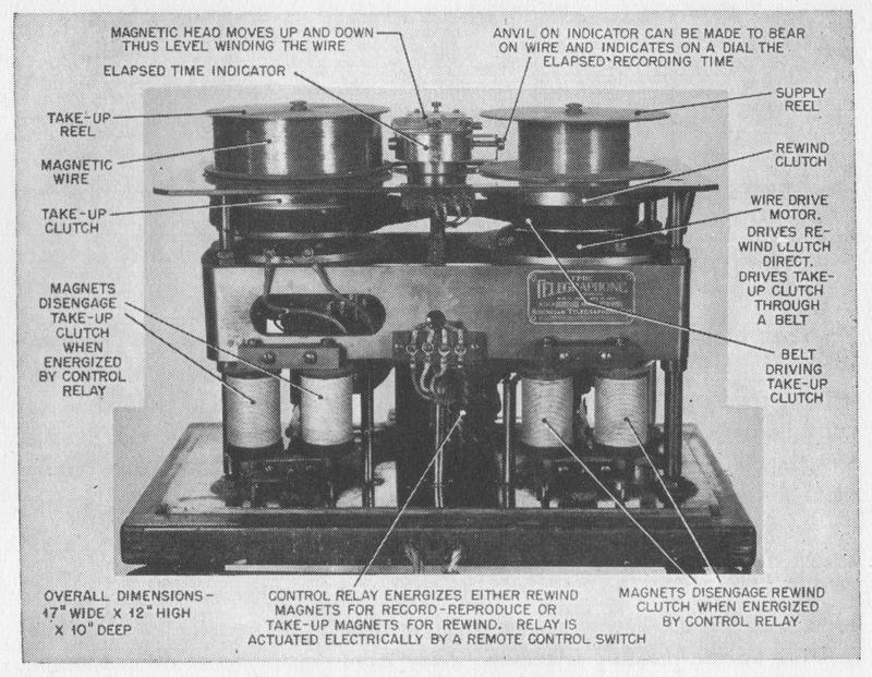
FIG. 6-1. The Telegraphone.


the head that was previously used for recording was connected to a telephone receiver. Sufficient wire was contained on removable reels for a half hour of continuous operation. A hinged double pole-piece head, permitting easy insertion and removal of the wire, was employed. The head, which traveled up and down for level winding, was operated by a heert-shaped cam. Directcurrent bias was employed.

The Telegraphone had many features that were to make it particularly suitable as a dictating machine. Its operations could be controlled from a remotely located station, and installations were suggested and in some instances made in which all wire recorders were placed in a central office and connected by cable to the different control boxes in the offices of the dictators. Each station was equipped with an indicator to inform the user how much recording time was still available. A foot pedal could be attached to the instrument to facilitate transcribing of a recorded message. When the typist pressed the stop pedal, the direction of the wire was automatically reversed for a short time, and only then did the medium come to rest. By this means, the last few words of the message were repeated before the subsequent portion was reproduced when the start pedal was operated.

page 137

Some of these instruments, which are still in existence, perform remarkably well.

Armour Wire Recorder

ARMOUR WIRE RECORDER. The Armour Research Foundation wire recorder model 50, shown in Fig. 6-2, was developed in the early 1940's by Marvin Camras. This recorder employed a nonconstant-speed drive, the reels themselves being driven through suitable clutches by one motor and supplying the entire motive power to the wire. The reels had a diameter of 33/4 inches. The playing time was either 1/2 or 1 hour, depending upon the speed of the medium which could be set for either 5 or 21/2 ft. per sec. Erasing was accomplished by means

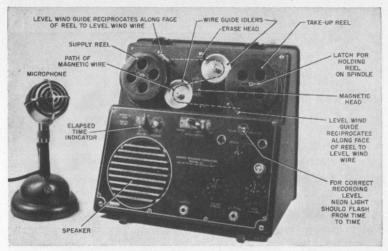
FIG. 6-2. Armour Research Foundation wire recorder (Model 50). (Courtesy of Armour Research foundation.)


of a solenoidal head, through which the 0.004-inch wire was threaded. The recording head was of the ring-type structure with a gap length of about 2 to 3 in us. Alternating-current biasing and erasing were employed. The bakelite supply and take-up reels were removable. The head remained stationary in this instrument, level winding being accomplished by guide fingers associated with

each reel. A revolution counter served as a time indicator to facilitate the find-II, of any recorded portion of the wire. The amplifier and loudspeaker were housed together with the drive mechanism. An instrument similar to the one shown in Fig. 6-2 was manufactured by the General Electric Company and was used by different branches of tile armed services.

page 138

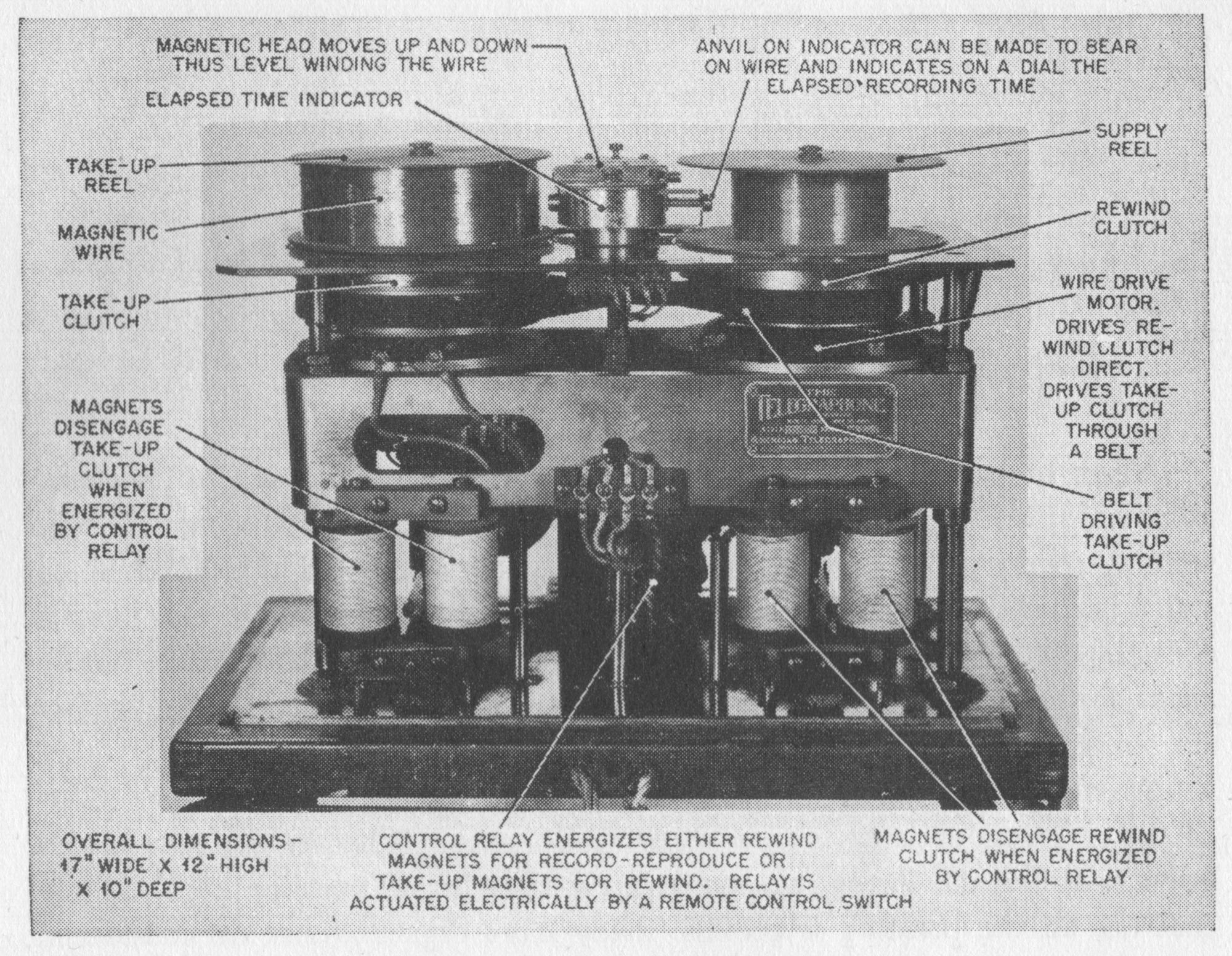
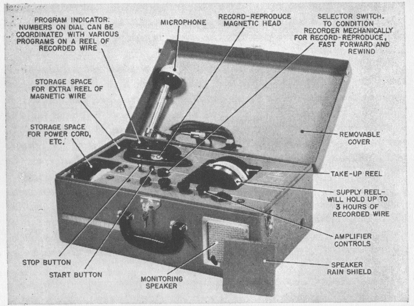
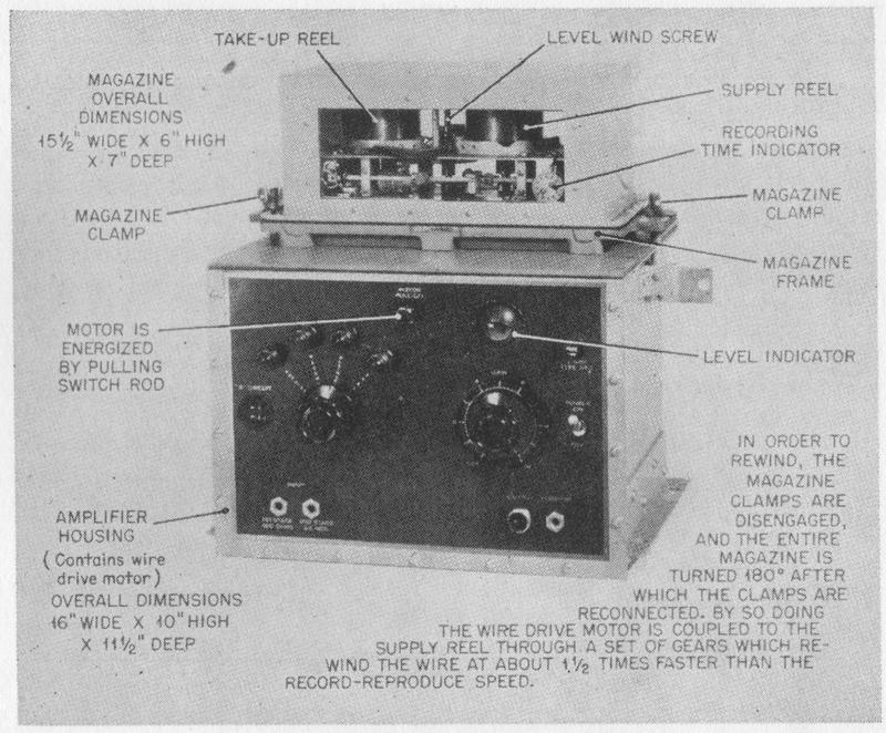
FIG. 6-3. Navy wire recorder with wide frequency range. (Courtesy of The Brush Development Company.)

Brush Navy Wire Recorder


NAVY WIRE RECORDER. The Navy type KS12016 wire recorder shown in Fig. 6-3 was produced by The Brush Development Company during the war and served as a basis for designs of other magnetic-recording equipment which was used by various branches of the armed forces. This wire recorder is significant in that it was the first magnetic recorder where the recording medium was housed in a totally enclosed magazine. This magazine was attached to the portion of the instrument containing the drive motor and the amplifier section. The 750-r.p.m. motor was directly coupled to the take-up reel spindle during recording and reproduction. For rewinding, the magazine had to be removed and rotated to engage the rewind spindle to the motor. A step-up gear in the magazine gave a rewind-forward ratio of 1.6 to 1.

A ring-type recording head and solenoidal erasing head, together with a level-wind mechanism, elapsed-time indicator, and automatic stop, were built into the magazine, which is shown with its case removed in Fig. 6-4. Electrical connections were made to the magazine by means of plug-type connectors.

The recording medium was 0.006-inch 420-type stainless steel wire and its

page 139

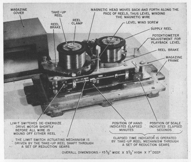
FIG. 6-4. Magazine for Navy wire recorder.


speed increased from a minimum of 5 ft. per sec. to a maximum of 7.5 ft. per sec. Mechanical brakes in the magazine tensioned the wire during operation and prevented unreeling while the magazine was removed.

Peirce Dictation Wire Recorder

PEIRCE DICTATING EQUIPMENT. The Peirce Dictation Wire Recorder (model 55B), shown in Fig. 6-5, is manufactured by the Peirce Wire Recorder Corporation. The design of this instrument is in many respects similar to the model 50 Armour wire recorder. It employs a nonconstant-speed drive system with certain refinements and additions to permit convenient dictation and transcription. In transcription of recorded material, the typist can stop the spools almost instantly by depressing a foot switch and can cause the machine to rewind a short distance and repeat the last few words by depressing another switch. The nominal wire speed is 2-1/2 ft. per sec., and the spools hold sufficient wire to permit a continuous hour of recording. The rewind-forward ratio is about 4 to 1. For rewinding a spool more rapidly, a separate rewinding device is provided. Both the supply and take-up reels are removed from the dictation device and placed on this rewind device, which will rewind an entire hour's recording in 7 min.

page 140

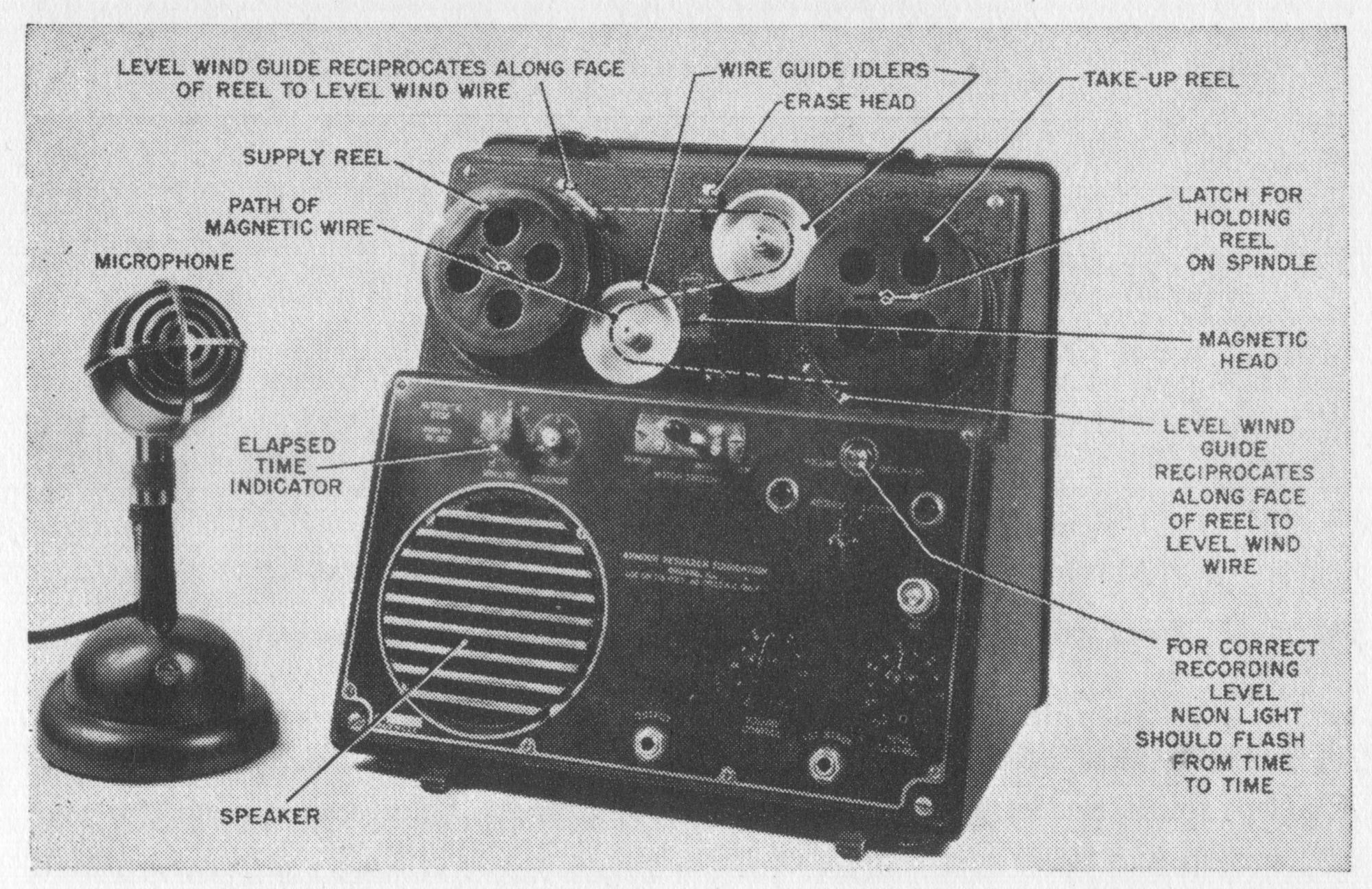
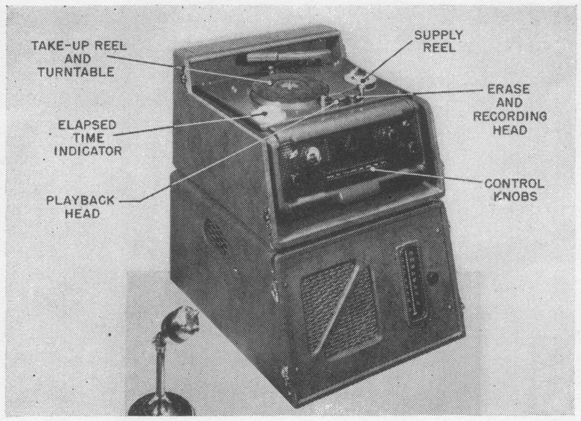
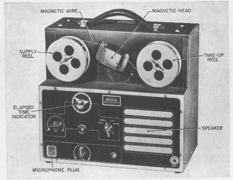
FIG. 6-5. The Peirce dictation wire recorder (Model 55-B). (Courtesy of Peirce Wire Recorder Corp.)


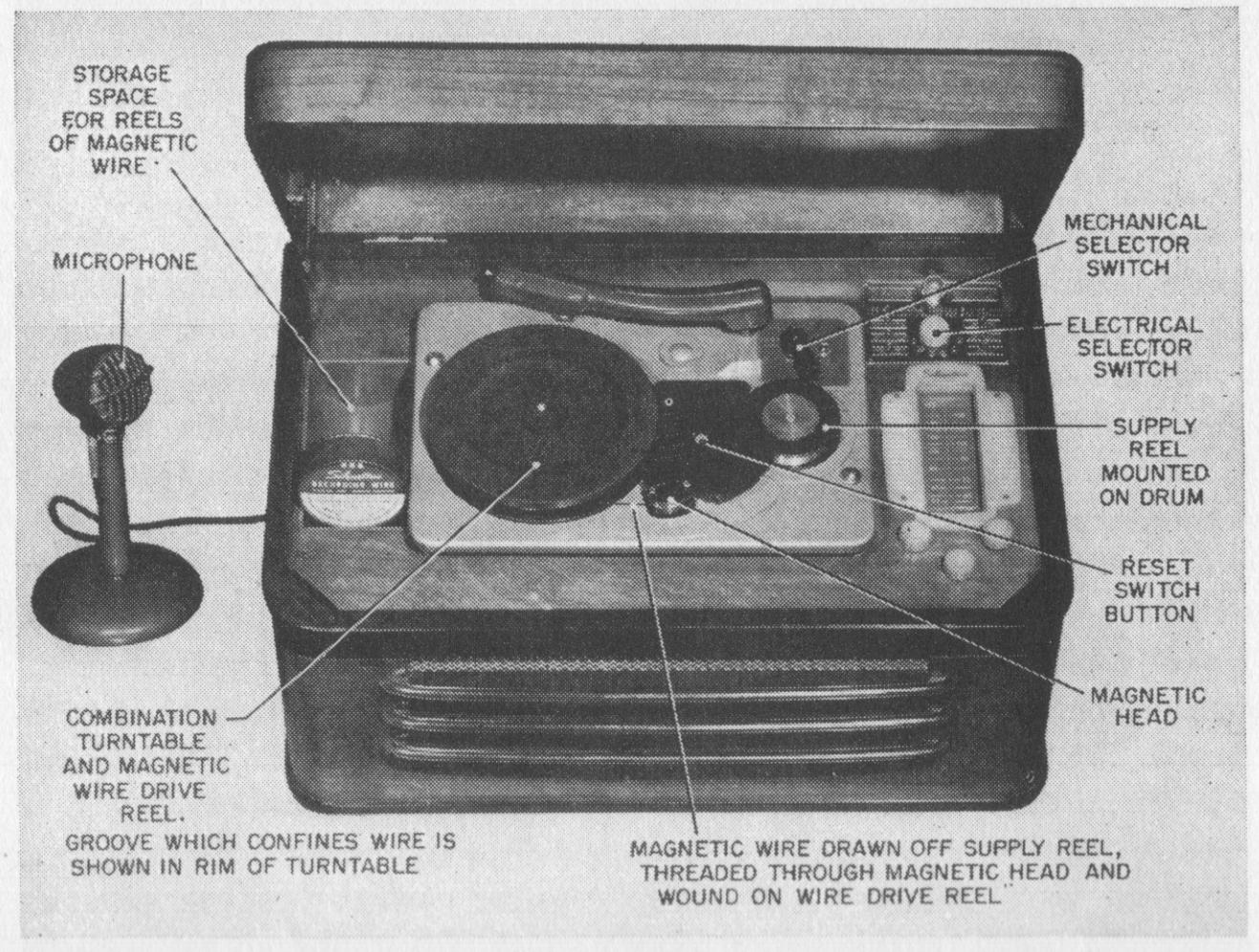
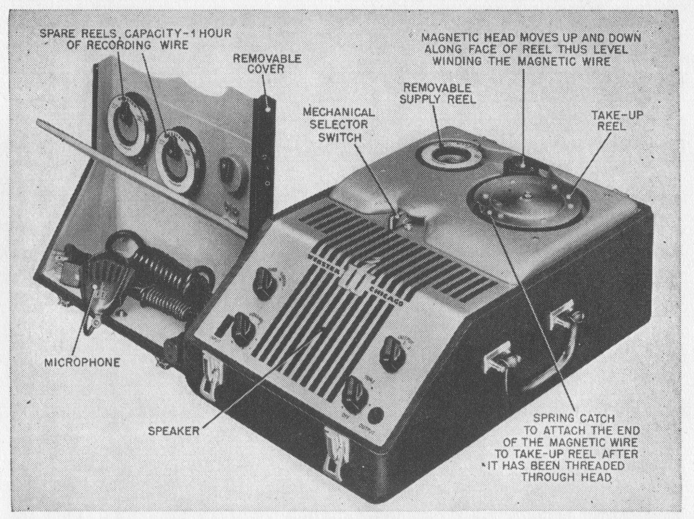
FIG. 6-6. Silvertone wire recorder-radio-phonograph combination. (Courtesy of Colonial Radio Corp.)
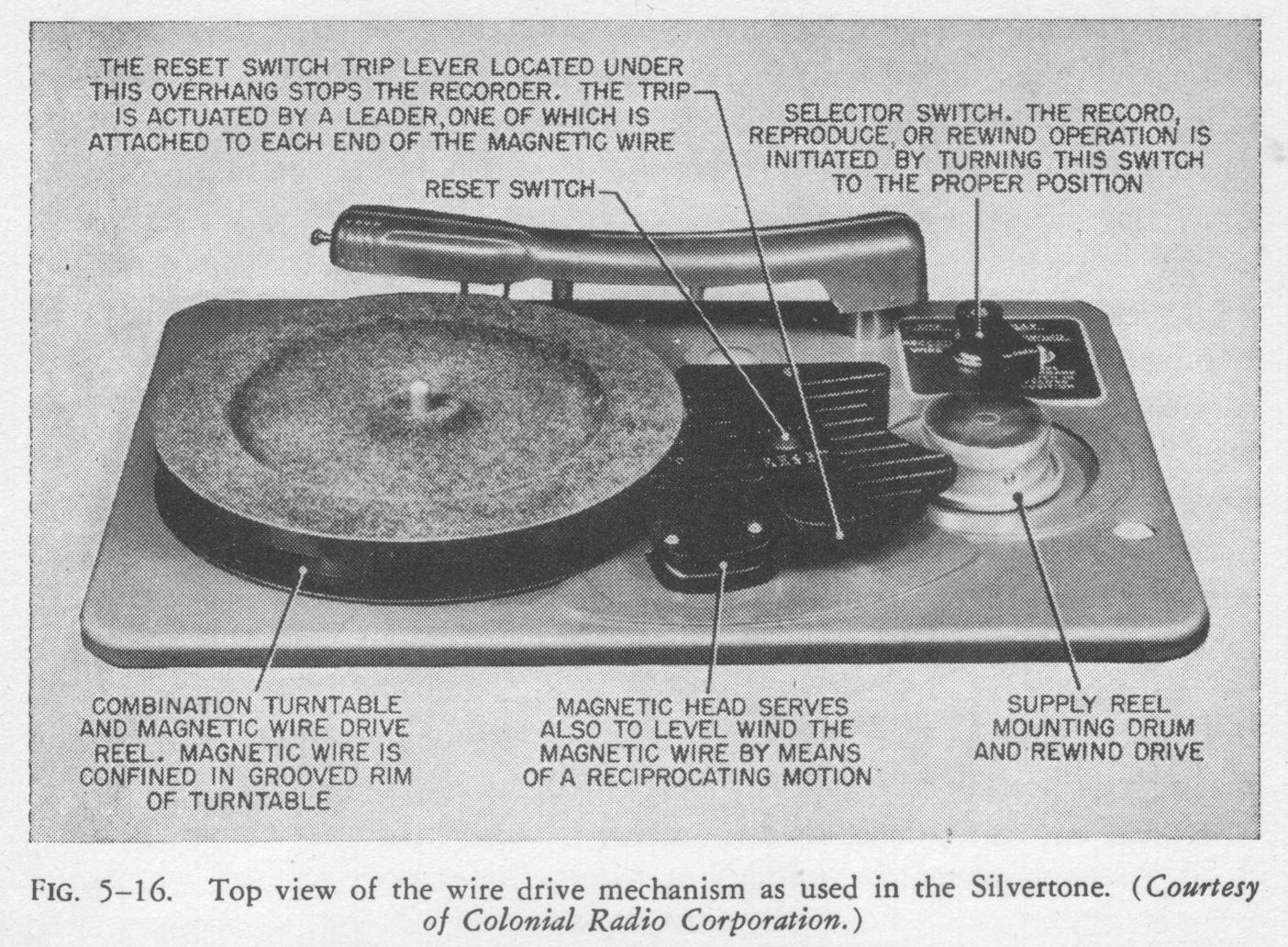
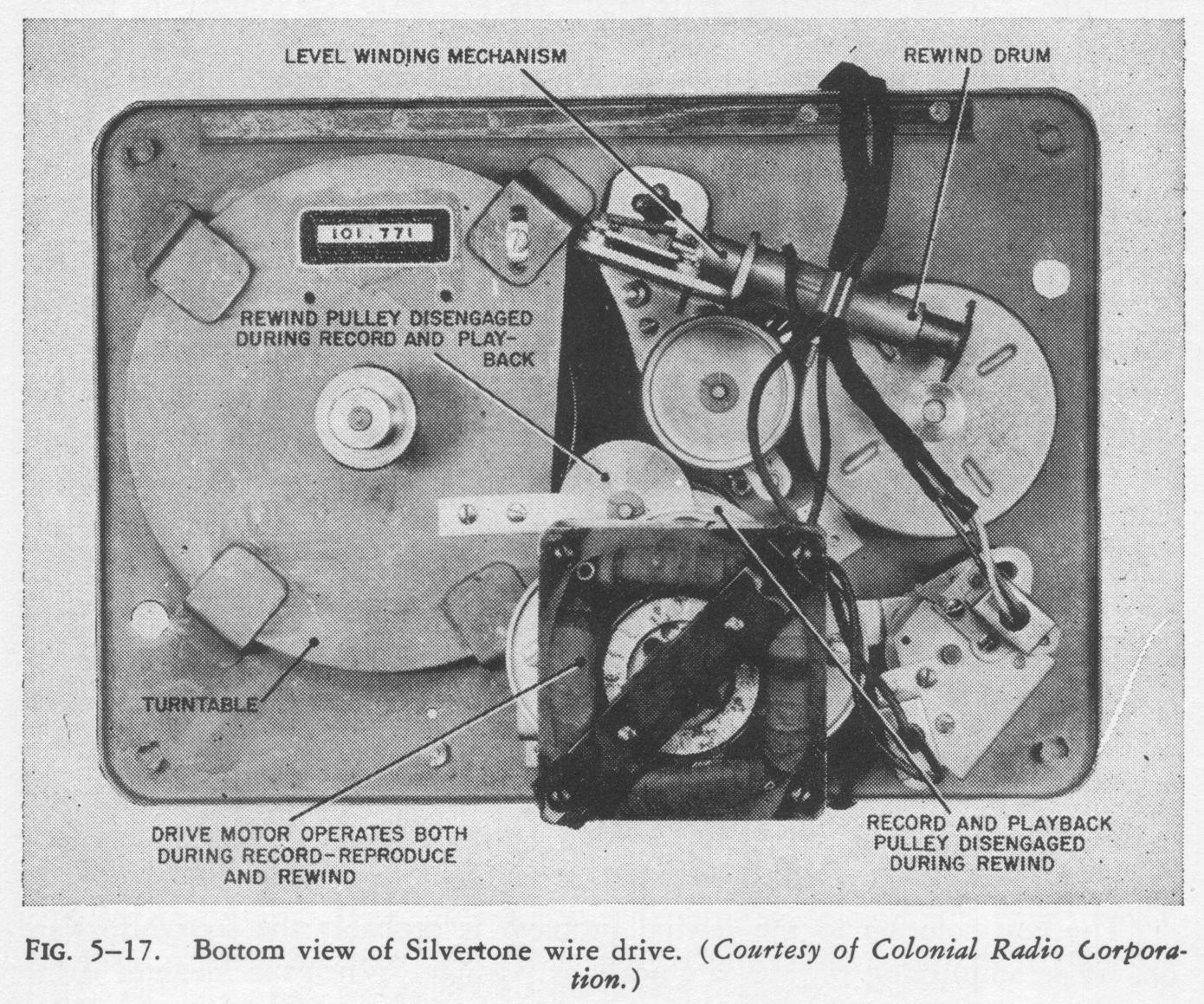
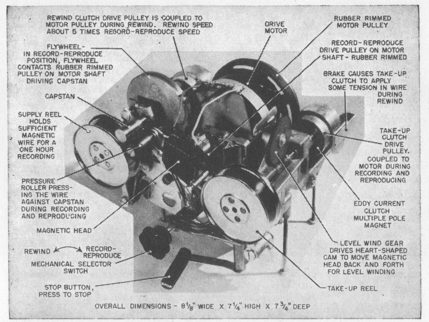
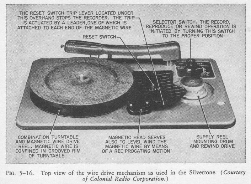
page 141

FIG. 5-16. Silvertone top view.
FIG. 5-17. Silvertone bottom view.

Silvertone Wire Recorder

"SILVERTONE" TABLE-MODEL WIRE-RECORDER COMBINATION. The Silvertone combination wire-recorder-radio- phonograph shown in Fig. 6-6 is marketed by Sears, Roebuck and Company. The top view of the basic wirerecorder unit of this instrument is shown in Fig. 5-16, its rear view in Fig. 5-17. The basic unit combines a phonograph and a wire recorder, the rim of the phonograph turntable being used as the take-up reel for the wire-recorder portion. The wire recorder employs a nonconstant-speed drive system, but because the diameter of the take-up reel is large, the variation in the speed of

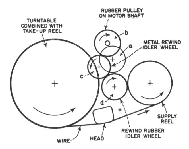
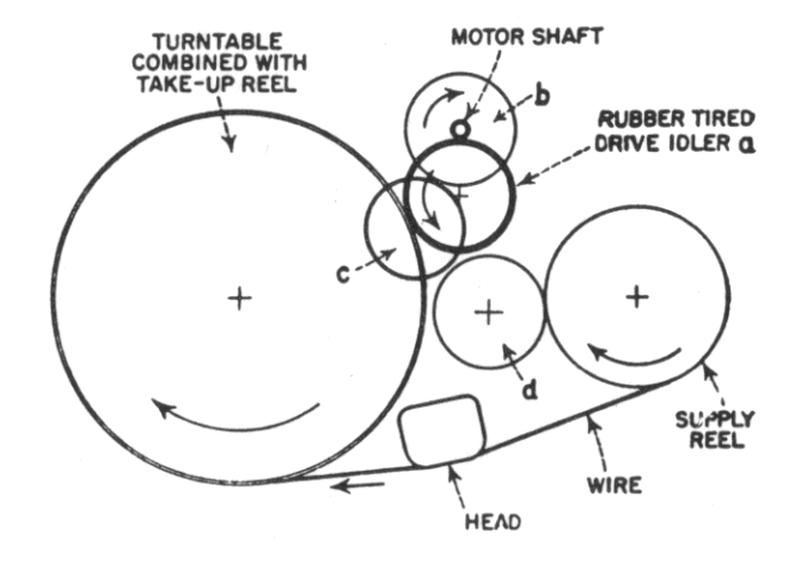
FIG. 6-7. Silvertone wire-recorder drive mechanism in record and playback position. Through idler a, the motor drives the turntable with an angular sped of approximately 78 r.p.m. The wire winding diameter of the turntable is sufficiently large so that the average linear velocity of the wire is about 2 ft. per sec. (Idler c is disengaged.) (Courtesy of Colonial Radio Corp.)
FIG. 6-8. Silvertone wire-recorder drive mechanism in rewind position. Through idlers c and d, motor pulley b drives the supply reel so that wire is rewound in about one fifth of the recording time. (Idler a is disengaged.) (Courtesy of Colonial Radio Corp.)


the wire from the beginning to the end of the recording period is only a few per cent. The recording medium is 0.004-inch 18-8 stainless steel wire, which is driven at a nominal velocity of 2 ft. per sec. The drive mechanism is shown diagrammatically in Figs. 6-7 and 6-8. The rewind-forward ratio is approximately 5 to 1. A removable supply reel holding enough wire for 1 hour of recording time can be rewound in 12 mm. The take-up reel, however, is not removable, and a recording must be completely rewound before a new supply reel can be inserted. Recordings can be made from a microphone, from the radio, or from records that can be played on the turntable at the same time the wire recorder is functioning. A neon bulb is used as a recording-level indicator, occasional flashing on at the loudest peaks being an indication that the recording is being made at the proper level.

page 142

Plastic leaders slightly wider than the distance between the flanges of the reels are attached to each end of the recording medium. These leaders have serrated edges that actuate a stop switch when they come in contact with it, and they have the further advantage of greatly facilitating the operation of connecting the wire to either the supply or take-up reel, since by simply pressing the leader in between the reel flanges enough frictional force is developed to hold them in place.

SILVERTONE CONSOLE WIRE-RECORDER COMBINATION. The Silvertone console, manufactured for Sears, Roebuck and Company by the Colonial Radio Corporation and shown in Fig. 6-9, employs a basic wire-recorder unit similar to that of the table-model combination described above, but it has a separate

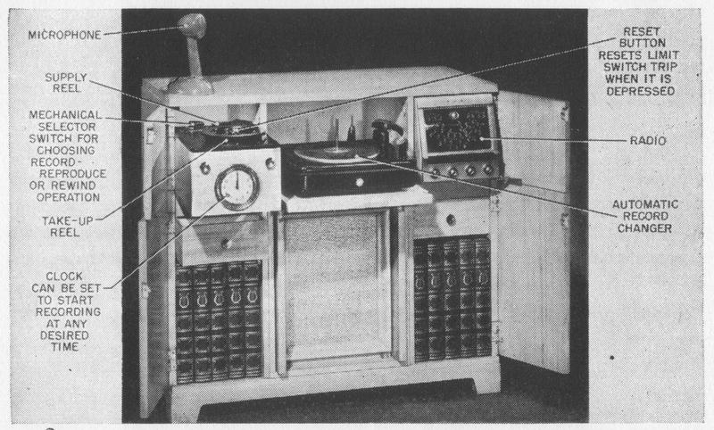
FIG. 6-9. Silverrone console combination. (Courtesy of Colonial Radio Corp.)


phonograph and record changer to permit the automatic playing of a number of records. The phonograph pickup arm, which is included as an integral part of the wire recorder in the table model, is, therefore, omitted in this model. A feature of considerable utility in the console model is the inclusion of an electric timing device which will start and stop the wire recorder at predetermined times. By means of this device, it is possible to record a desired radio program even though no one is present at the time the program is being broadcast.

Majestic Wire Recorder

MAJESTIC WIRE-RECORDER COMBINATION. The Majestic wire recorder is in appearance similar to the Silvertone table-model combination. A schematic drawing of the wire-recording mechanism is shown in Fig. 6-10. The instrument employs two motors. The play-record motor is coupled to the take-up reel

page 143

by means of a removable idler, and the rewind motor is coupled directly to the shaft of the supply reel. The rewind-forward ratio for this machine is about 6 to 1.

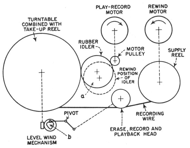
FIG. 6-10. Majestic wire-recorder drive mechanism. For recording and reproducing, idler a couples the motor pulley to the combination turntable and take-up reel. For rewinding, a is disengaged and the rewind motor is energized. The removable supply reel is attached to the rewind motor shaft. A heart-shaped cam b driven by the turntable shaft moves the magnetic head up and down for level winding.
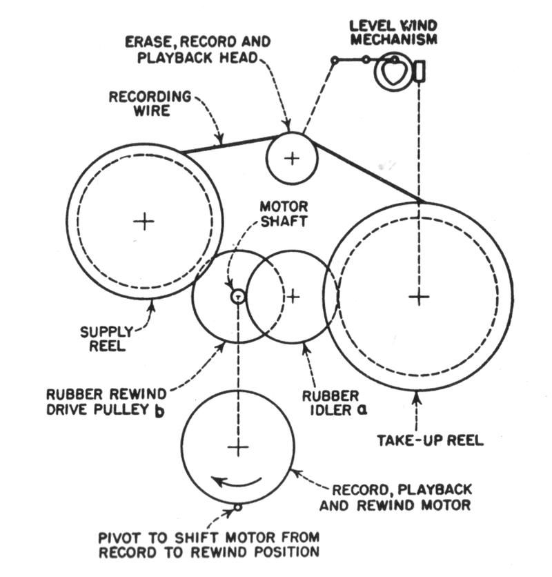
FIG. 6-11. Webster wire-recorder drive mechanism. For recording and reproducing, the motor shaft is pressed against idler a and drives the take-up reel. For rewinding, the motor is shifted, and the drive pulley b is coupled to the supply reel. A slowly rotating heart-shaped cam moves the bead structure up and down for level-winding the wire.


Webster Wire Recorder

WEBSTER WIRE RECORDER. The Webster model 80 wire-recorder, manufactured by Webster-Chicago, employs the drive mechanism shown schematically in Fig. 6-11, in which the position of a pivotally mounted motor determines the forward or rewind function. The wire speed is nonconstant, but by the use of a relatively large diameter take-up reel, variations in speed of the medium between the beginning and end of a recording period are minimized. Only the supply reel is removable, thus necessitating completely rewinding a recording before reels can be changed. No automatic stop mechanism is provided. The design emphasizes portability, and the instrument shown in Fig. 6-12 is housed in a carrying case approximately the size of a portable typewriter. No volume-level indicator is included in the instrument for monitoring the level during the recording period to prevent over- or undermodulation, but a separate

page 144

FIG 6-12. Webster wire recorder. (Courtesy of Webster Electric Co.)


unit is available and terminals are provided in the instrument for connecting it if so desired. The recording medium is 18-8 stainless steel wire 0.0036 inch in diameter, driven at a nominal speed of 2 ft. per sec. and is available in 1/4- 1/2-, and 1-hour spools. Level winding is accomplished in this instrument by moving the head up and down on its shaft by means of a heart-shaped cam in the drive system, the movement of the head serving to distribute the wire evenly on the take-up reel. Rewind-forward ratio for this machine is about 5 to 1.

WiRecorder-Gaylord Wire Recorder

WIRECORDER. The model PA WiRecorder, which is manufactured for the WiRecorder Corporation by the Gaylord Manufacturing Company, is supplied either as a basic unit, shown in Fig. 6-13, or in the cased model shown in Fig. 6-14. This latter is not a complete magnetic-recording instrument, but is intended as an adjunct to a radio or public-address type of amplifier; it contains only the biasing-erasing oscillator and the necessary equalizing circuits. The drive mechanism is extremely compact. In distinction to the instruments described above it provides a constant-speed drive that propels the wire at a speed of 2 ft. per sec. by means of a capstan, with a rewind-forward ratio of 5 to 1. This drive mechanism, which is shown diagrammatically in Figs. 6-15 and 6-16, employs eddy-current clutches between the reel shafts and the two clutch-drive pulleys. The reel shafts are terminated in multipoled circular permanent magnets that rotate with a small clearance within copper cylinders. The copper cyl-

page 145

FIG. 6-13. Model PA WiRecorder drive mechanism. (Courtesy of WiRecorder Corp.)
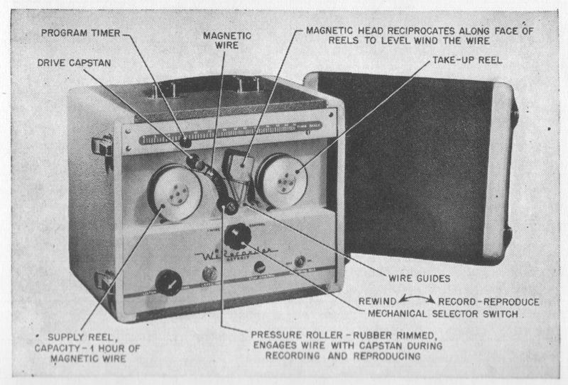
FIG. 6-14. Cased model of WiRecorder instrument shown in reqind position. (Courtesy of WiRecorder Corp.)
page 146

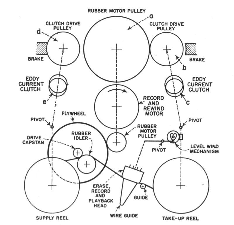
FIG. 6-15. WiRecorder drive mechanism in record and playback position. The motor pulley a drives clutch-drive pulley b. Eddy-current clutch c develops sufficient torque tending to overdrive take-up reel. Clutch-drive pulley d is held stationary by the brake, thus applying a brake load to the supply reel through eddy-current clutch a. Capstan propels the wire with constant speed (2 ft. per sec.) independent of diameter of take-up reel.
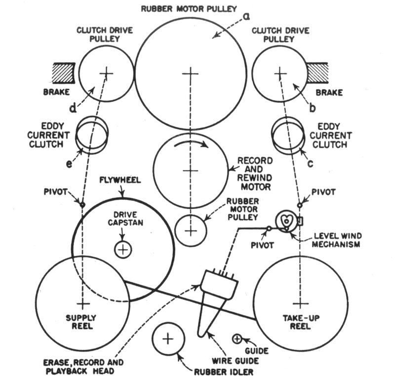
FIG. 6-16. WiRecorder drive mechanism in rewind position. Motor pulley a drives clutch-drive pulley d, while clutch-drive pulley b is held stationary. Eddy-current dutch e develops the necessary torque to drive the supply reel with high angular speed for re-winding, while eddy-current clutch c applies a brake load to take-up reel to maintain proper wire tension.


inders are themselves driven by the clutch-drive pulley, which is in engagement with the motor. As the copper cylinders rotate, the permanent magnets are caused to rotate by the fields of the eddy currents generated in the copper vinders. While the take tip reel is driven so that the wire is kept tinder tension

page 147

when it is fed from the capstan drive, the clutch-drive pulley on the supply-reel side is maintained stationary by the application of a mechanical brake. The eddy-current clutch provides in this case a braking effect for maintaining steady tension.

The wire is level-wound on the reels by means of a heart-shaped cam which drives the recording-reproducing head back and forth at a constant speed, distributing the wire evenly on the spools. Both the capstan drive and the pressure pulley that forces the wire against it are of sufficient width to permit the wire to travel back and forth under the impetus of the level wind mechanism. The fact that the wire travels back and forth continuously along capstan and pressure pulley minimizes wear on their surfaces, a condition that would otherwise be difficult to achieve. The reels hold sufficient wire for 1 hour of recording.

An automatic-stop mechanism is provided to prevent the wire from being completely unwound from either reel. A lightweight lever is inserted into the hub of each reel drum and is normally held in position there by the pressure of the wire layers. When only about half the last layer remains on the bottom of the reel, this lever is released and, propelled by centrifugal force, engages a stop switch.

Magnetone Wire Recorder

MAGNETONE. The model BK-303 Magnetone portable wire recorder shown in Fig. 6-17 is manufactured by The Brush Development Company and is designed primarily for applications where long playing time is essential. A continuous 3-hour recording may be made on this instrument.

The recording medium consists of 0.0046-inch-diameter plated wire, capstandriven at a constant speed of 2 ft. per sec. One reel is removable, permitting storage of recorded program material.

The drive system is shown diagrammatically in Fig. 6-18. The reels are not directly driven, the entire motive power for the medium being supplied by the capstan. The reels are connected together by means of a differential-drive mechanism, as shown, which is discussed in the chapter on components. As wire is drawn off the supply reel by the capstan, the supply reel drives the take-up reel. During the rewind period the relationship is automatically reversed, the take-up reel driving the supply reel. The differential adjusts automatically to maintain the wire under constant tension at all times. One very desirable feature of such a drive system is the fact that in the event the wire breaks, the propelling power on the wire is removed and the reels come to a stop almost immediately, thereby preventing wire from being thrown from the spools.

Level winding in this drive system is achieved by mounting the entire differential mechanism, including the take-up and supply reels, on a shaft cut with a reversing thread. As the reels revolve, the reels and differential move back and forth on this shaft, causing the wire, which leaves the capstan with a given speed at a constant angle, to be level-wound on the reels. A relatively high rewind

page 148

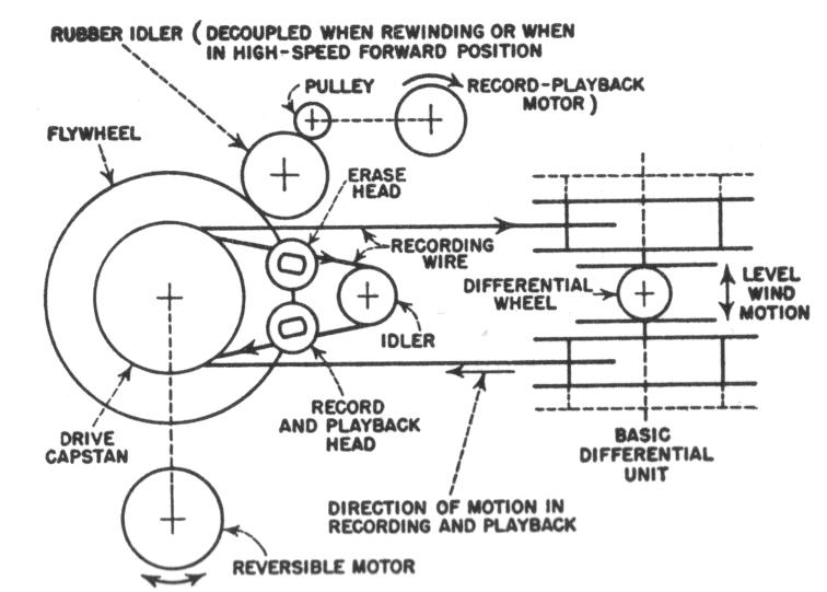
FIG. 6-17. Magnetone (Model BK-303) portable wire recorder. (Courtesy of The Brush Development Company.)
FIG. 6-18. Magnetone Model BK-303 using the same differential unit as shown in Figs. 6-19 and 5-15. The capstan is mounted on the shaft of a reversible motor, which drives the wire with high speed in either direction. The reversible motor idles during recording and reproducing.


and forward speed, which is about fifteen times the recording speed, is achieved in this drive system by uncoupling the record-playback motor from the capstan and driving the capstan from a high-speed reversible motor.

Level is indicated during the recording period by the pattern of a magic-eye tube. The instrument is equipped with separate gain controls for recording andpage 149

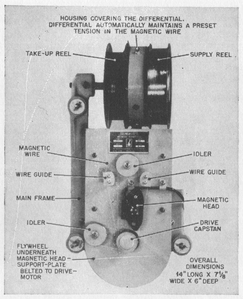
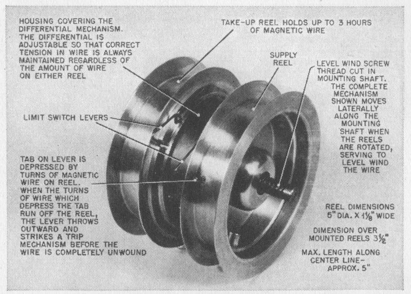
FIG. 6-19. Differential unit and automatic stop mechanism of Magnetone wire recorder. (Courtesy of The Brush Development Company.)


playback. An indicator attached to the capstan shows elapsed recording time, permitting convenient identification of any particular section of the recording. To prevent the wire from being inadvertently completely unwound from either reel, an automatic stop mechanism is provided, which consists of spring-biased latches set into the reel-mounting drums that are located beneath corresponding openings in the reels themselves (Fig. 6-19). These latches are kept depressed by the wire wound on the reels for as long as any wire lies above the latches. When the wire is unwound from the latches, they are projected upward by their spring bias and centrifugal force and engage the stop switch.

Railroad Wire Recorder

RAILROAD RECORDER. The so-called "Railroad Recorder," shown in Fig. 6-20, is a basic unit designed to be used in groups of two or more to provide continuously repeating programs with a cycle of 6, 9, 12, or more hours, depend-ing on the number of units employed. Manufactured by The Brush Development Company, it uses the same differential mechanism as the model BK-303 Magnetone, together with the capstan-drive system shown schematically in Fig. 5-14. No provision is made for fast rewind or elapsed-time indication. The recording of program material on plated wire is done elsewhere, these units being designed solely for playback purposes. Hence, only a playback head is provided, In erasing head not being necessary. The primary impetus to develop this instrument came from transportation companies who desired to supply their patrons with music as a means of lightening the tedium of the journey. Phonograph recordings and the radio both provide an inadequate answer to this problem: phonograph records, because they are

page 150

FIG. 6-20. Railroad wire recorder (see also Fig. 5-14). (Courtesy of The Brush Development Company.)


bulky and cannot be played in the presence of severe jolting or vibration, and the radio, because the constant change in location requires frequent retuning.

In use, two or more units are interconnected by means of relays, so that when one unit completes playing, a second unit immediately starts to play and the first unit begins to rewind. Since there is no advantage in fast rewind, this operation takes place at the same rate as the "forward" motion and is completed at about the same time that the second unit completes its playing cycle. At this point, if only two units are employed, the first unit again plays and the second rewinds, thereby eliminating any substantial break in the program. If three units are employed, the third plays while the second rewinds, and the first plays while the third rewinds. A special feature of the Railroad Recorder consists in the fact that in the event the wire breaks, a switch is actuated which throws the damaged unit out of the chain and puts the next unit in operation.

Lear Dynaport Wire Recorder

LEAR DYNAPORT. The Lear Dynaport, manufactured by Lear, Inc., is shown in Fig. 6-21. It uses stainless-steel wire as the recording medium, which is driven by a pseudo constant-speed drive mechanism at about 2 ft. per sec. The drive is powered by a hysteresis synchronous motor. A 1-hour recording can be fast-wound in each direction within 3 min. The take-up reel also serves as a turntable for playing of disc records The phonograph pickup arm is part of the instrument.

page 151

FIG. 6-21. Lear Dynaport placed on radio and amplifier cabinet. (Courtesy of Lear, Inc.)


Three heads are used. The erasing and recording heads are combined in one housing, and the playback head is a separate unit. The heads are moved up and down to distribute the wire evenly across the winding surfaces of both reels. An elapsed-time indicator is calibrated from 0 to 60, and its accuracy is claimed to be within 10 sec.

Master-Nemeth Wire Recorder

MASTER WIRE RECORDER. The Master Wire Recorder as manufactured by Otto R. Nemeth, Inc., is shown in Fig. 6-22 with its case removed. It features a magazine in which the recording medium moves with a constant speed of 2 ft. per sec. Constant-speed Qperation is obtained by the use of a "self-locking wedge drive." In this particular drive, the wire is tightly engaged by a wedge-like groove in the capstan pulley without requiring additional pressure means. The magazine houses the two wire reels and an elapsed-time indicator that stops the drive when the wire on either reel is about exhausted. In fast forward and rewind position, the wire moves from one reel to the other in a straight line with-

Lit contacting the drive, the level-wind pulley, and the magnetic head, as shown schematically in Fig. 6-23. These three elements, namely, the drive pulley, the level-wind pulley, and the head, are mounted on a turret, as shown in Fig. 6-24. The turret is turned about 200 deg. for recording or playback. The wire is then (ilgaged in its path from the supply to the take-up reel, so that it now moves with the appropriate speed, contacting the head and being properly level-wound

nto the rake-up reel. During fast reeling the wire does not engage the levelwind pulley, and the wire distribution on the reel from which the wire is withfr.iwn onirnic th l'vrl winlitii' on the reel on which the wire is wound. Three

page 152

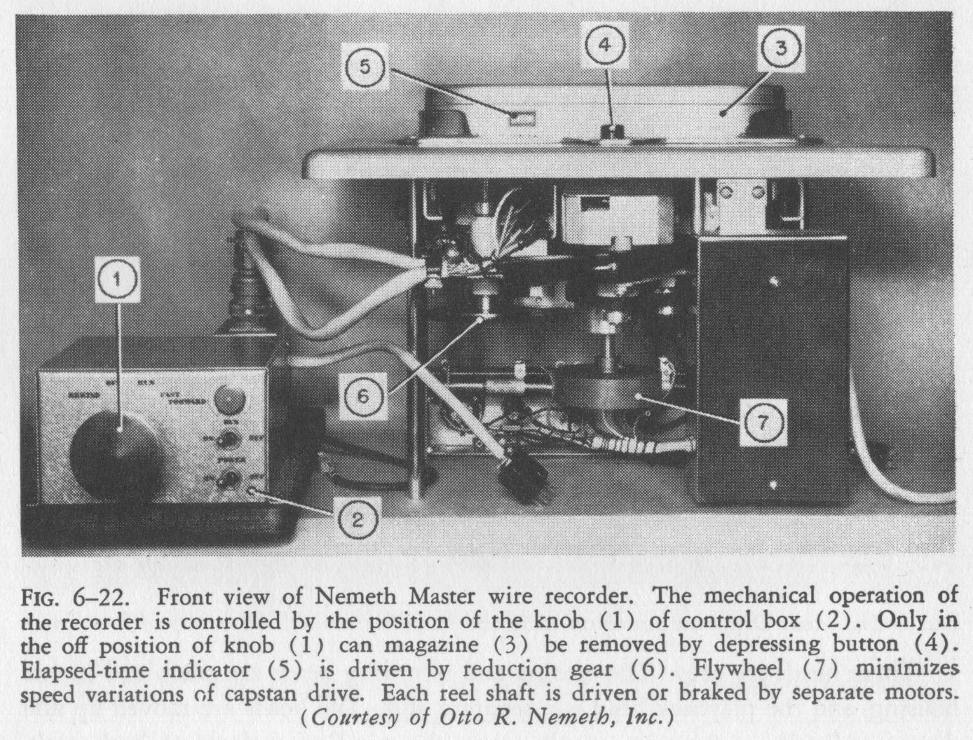
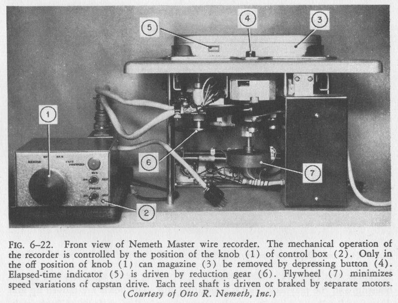
FIG. 6-22. Front view of Nemeth Master wire recorder. The mechanical operation of the recorder is controlled by the position of the knob (1) of control box (2). Only in the off position of knob (1 can magazine (3) be removed by depressing button (4). Elapsed-time indicator (5) is driven by reduction gear (6). Flywheel (7) minimizes speed variations of capstan drive. Each reel shaft is driven or braked by separate motors. (Courtesy of Otto R. Nemeth, Inc.)
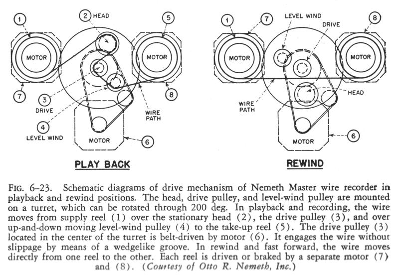
FIG. 6-23. Schematic diagrams of drive mechanism of Nemeth Master wire recorder in playback and rewind positions. The head, drive pulley, and level-wind pulley are mounted on a turret, which can be rotated through 200 deg. In playback and recording, the wire moves from supply reel (1) over the stationary head (2), the drive pulley (3), and over up-and-down moving level-wind pulley (4) to the take-up reel (5). The drive pulley (3) located in the center of the turret is belt-driven by motor (6). It engages the wire without slippage by means of a wedgelike groove. In rewind and fast forward, the wire moves directly from one reel to the other. Each reel is driven or braked by a sparate motor (7) and (8). (Courtesy of Otto R. Nemeth, Inc.)
page 153

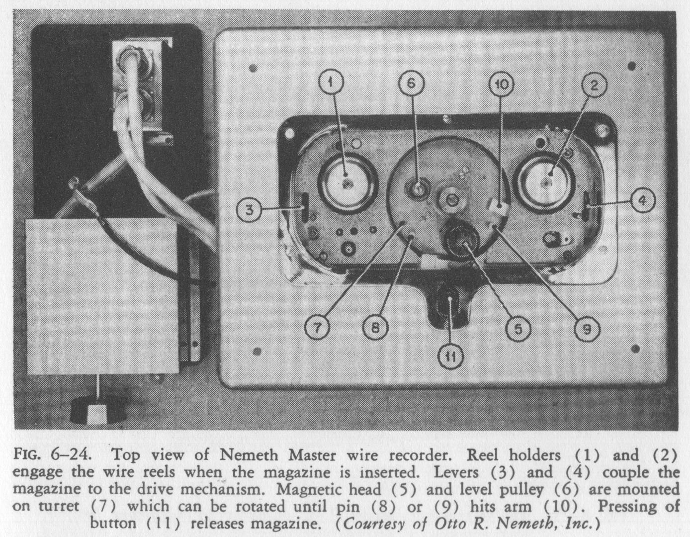
FIG. 6-24. Top view of Nemeth Master wire recorder. Reel holders (1) and (2) engage the wire reels when the magazine is inserted. Levers (3) and (4) couple the magazine to the drive mechanism. Magnetic head (5) and level pulley (6) are mounted on turret (7) which can be rotated until pin (8) or (9) hits arm (10). Pressing of button (II) releases magazine. (Courtesy of Otto R. Nemeth, Inc.)


motors are used in the drive mechanism; one motor each drives the supply and take-up reel shaft and the third motor drives the drive pulley. Depending upon the direction of operation, one or the other reel shaft motor is electrically braked to maintain proper tension of the wire. The head housing contains an erasing and recording-reproducing head and is of the plug-in type, permitting easy interchangeability.

The magazine can only be inserted or removed in the off position of the drive mechanism. It is automatically locked and requires the pressing of a button for removal. Essentially the same mechanism is used in the Dicta-Wire Recorder manufactured by the Standard Business Machine Company.

Magnecorder Wire Recorder

MAGNECORDER. The Magnecorder model SD-1, shown in Fig. 6-25, is manufactured by Magnecord, Incorporated. The recording medium is a 0.004inch stainless-steel wire and is capstan-driven with a velocity of 4 ft. per sec. by synchronous motor. Both wire reels are removable. The instrument has a recording time of slightly more than 30 mm., and its over-all frequency response reported to be within 2 db. from 50 to 12,000 c.p.s. This recorder has been designed to meet broadcast requirements. Input and output impedances are (00 ohms, and a VU meter is used for level indication. An elapsed-time indicator provided.

Armour Master Wire Recorder

ARMOUR MASTER RECORDER. The Armour Master Recorder shown in Fig. 6-26 is an experimental unit developed at the Armour Research Founda-

page 154

tion for use in broadcast and transcription applications. The recording medium is stainless-steel wire, capstan-driven with a speed of approximately 5 ft. per sec. A frequency response within :t5 db. from 35 to 15,000 c.p.s., together with speed variations of less than 0.1 per cent, is reported for this instrument.

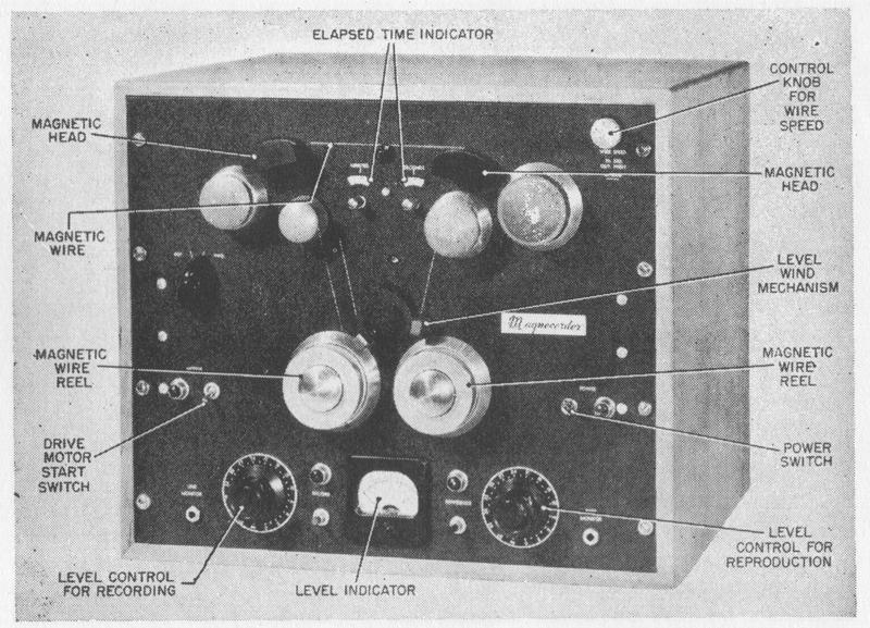
FIG. 6-25. The Magnecorder Model SD-1. (Courtesy of Magnecord, Inc.)
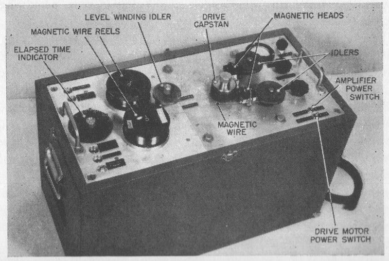
FIG. 6-26. Armour Master wire recorder. (Courtesy of the Armour Research Foundation).
page 155

Ipsophone Wire Recorder

IPSOPHONE. The Ipsophone, developed by the research division of the Oerlikon Machine-Tool Works of Buhrle and Company near Zurich, Switzerland, is a magnetic-recording device that automatically records and reproduces telephone messages. Although magnetic recording is almost ideally adapted to such service, and although telephone recorders have been manufactured in Europe for many years, the Ipsophone is the first device in which the many technical problems involved seem to have been solved to satisfaction.

The Ipsophone consists of two parts, a telephone handset mounted on a control box and a much larger housing containing the magnetic-recording apparatus, relays, amplifiers, and so on. Three complete magnetic-recording channels are included in the apparatus, one of which is used to answer the telephone when the subscriber is not present, and which provides a series of signals needed for remote control of the equipment. After the telephone rings a few times, a recorded message informs the caller that an Ipsophone is ready to record. The other two channels are provided for recording incoming messages. The recoring mechanism can be seen in Fig. 6-27. Of the two recording channels, one records for 5 mm. and the other for 25 mm. The purpose of this dual-channel recording arrangement is to reduce to a very short time the waiting period necessary during rewind. The rewind-record ratio for both units is 5 to 1, and with

FIG. 6-27. Mechanism of the Ipsophone Telephone Recorder. (Courtesy of Oerlikon Machine Tool Works.)
page 156

both reels empty, the 5 mm. reel is recorded first, after which all subsequent recordings are made on the second reel. As soon as the first reel is fully recorded, it rewinds automatically, ready to repeat immediately. When the repeat signal is given to the machine, the second reel rewinds while the first is playing. The maximum possible waiting time necessary for rewinding is thus only 1 mm.

The magnetic-recording apparatus, which employs steel wire for the recording medium, is straightforward. Of particular interest is the ingenious system of voice-operated relays that makes it possible for an Ipsophone subscriber to have his telephone messages repeated to him by telephone, without at the same time giving access to unauthorized persons. After the Ipsophone has announced that it is ready to accept a message, the calling party can by using a code word make the instrument start counting. The Ipsophone slowly repeats "one, two, three, ... ... ..., ten." The subscriber pronounces the words, "Hello, Hello," after three of these numbers, upon which the Ipsophone will repeat all recorded messages into the telephone. The subscriber can set the apparatus to respond to any three numbers he wishes, and the possible number of combinations is high enough so that secrecy is well assured.

STEEL-TAPE RECORDERS

Bell Labs Steel Tape Recorder

DEMONSTRATION VOICE RECORDER. A magnetic recorder using a short endless tape was built in 1936 by the Bell Telephone Laboratories as demonstration equipment to make it possible for any individual to listen to his own telephone voice. This instrument, which is shown in Fig. 6-28, was shown in many exhibitions and at the New York World's Fair.

TWO-CHANNEL MAGNETIC-TAPE RECORDER. The American Telegraph and Telephone Company demonstrated at the New York World's Fair a dual-channel magnetic recorder for showing the effect of binaural or stereophonic recording. Two tapes were wound together on the same supply and take-up reel.

FIG. 6-28. Hear-Your-Telephone-Voice Recorder. (Courtesy of the Bell Telephone Laboratories.)
page 157

These tapes were separated at the recording and erasing heads. Figures 6-29 and 6-30 show the top and rear view of the device.

Soundmirror Steel Tape Recorder

SOUNDMIRROR. The early model of the Soundmirror shown in Fig. 6-31, although no longer produced, is of some interest historically because of the fact that it was the first commercially successful magnetic recording device to be manufactured in the United States. Developed by Magnetone, Inc., the first Soundmirrors were built by Acoustic Consultants, of New York, and later in 1939 by The Brush Development Company. These instruments were marketed by Brush until this country's entrance into the war.

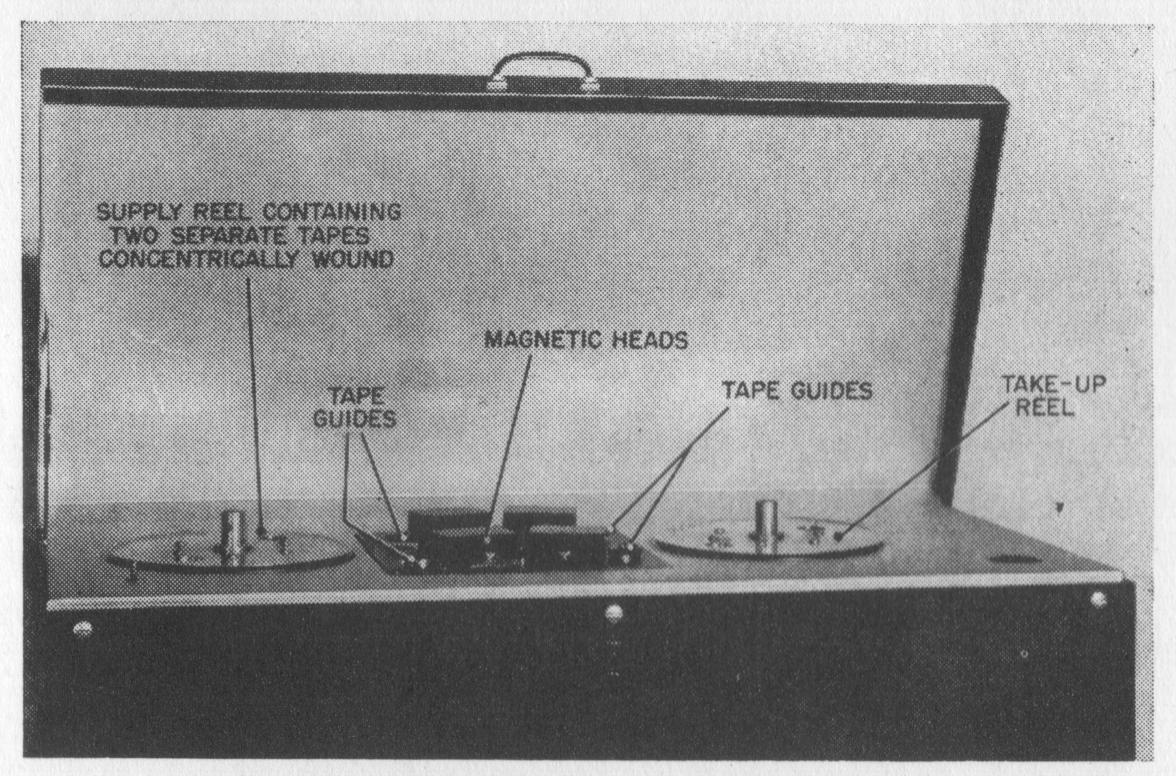
FIG. 6-29. Top view of two-channel stereophonic magnetic steel-tape recorder. (Courtesy of the Bell Telephone Laboratories.)


Tungsten-steel tape, 1/4 inch wide and propelled at a speed of 4.5 ft. per sec., was employed as the recording medium in this model. Sufficient tape was provided for a total recording time of either 1 or 2 mm. The tape was passed around four rollers to form an endless helical loop, as shown in Fig. 5-11, thus providing immediate playback at the end of the recording period. A crossover system connected the beginning and the end of the helix. The erasing and recordingreproducing heads employed double pole-piece construction. The recording channel was automatically shut off by an electrical timer after a recording was made to prevent accidental erasure.

This early Soundmirror was used as a voice-training and announcing device. The frequency response was substantially flat from 100 to 5,000 c.p.s, with a dynamic range ofabout 40db. A number of these unites are still in service.

page 158

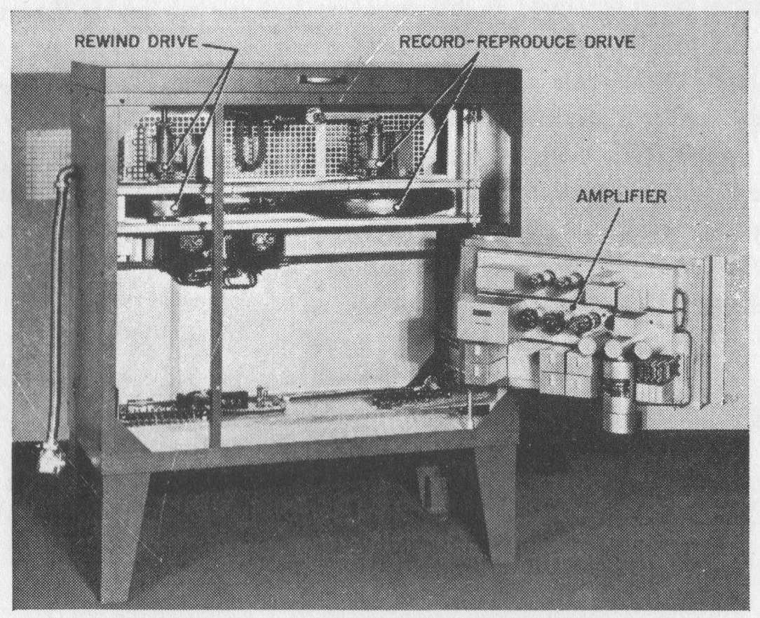
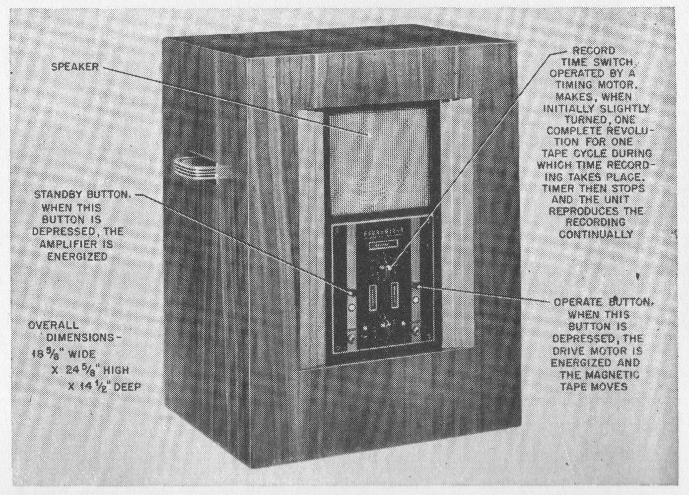
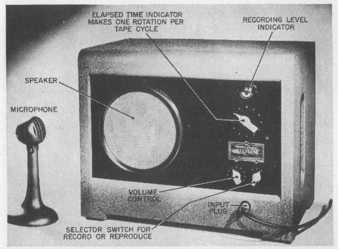
FIG. 6-30. Front view of two-channel stereophonic magnetic steel-tape recorder. (Courtesy of Bell Telephone Laboratories.)
FIG. 6-31. Soundmirror (see Fig. 5-11) (Courtesy of The Brush Development Company.).


page 159

Mirrophone Steel Tape Recorder

MIRROPHONE. The Mirrophone, shown in Fig. 6-32, was manufactured by the Western Electric Company in the beginning of 1940 and was intended primarily as a voice-training device and for use in the telephone system for weather-announcing purposes.

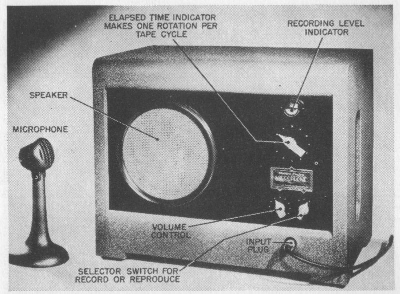
FIG. 6-32. Mirrophone. (Courtesy of Bell Telephone Laboratories.)
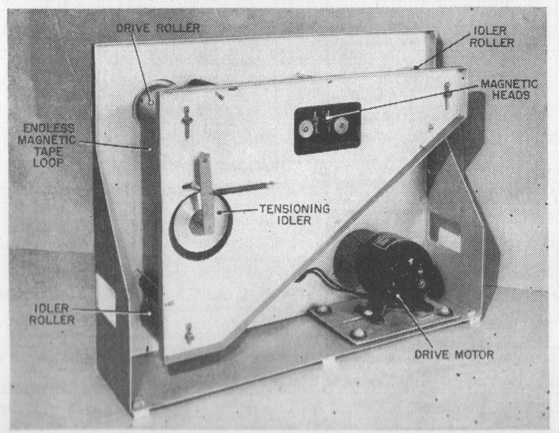
FIG. 6-33. Rear view of Mirrophone. (Courtesy of Bell Telephone Laboratories.)


page 160

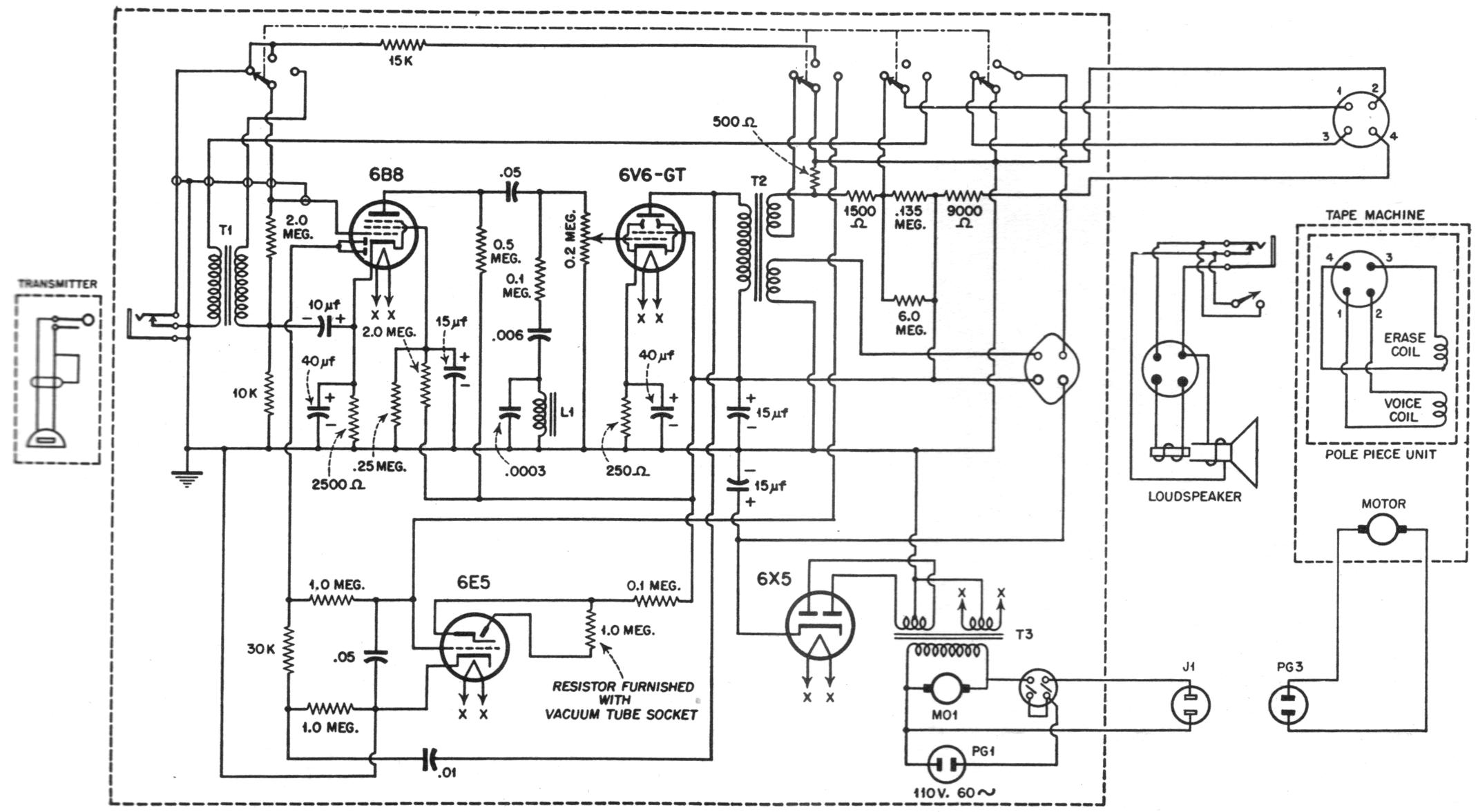
FIG. 6-34. Circuit diagram of Mirrophone. During recording, the grid of the 6B8 tube is connected to a crystal microphone. Magiceye tube 6E5 serves as level indicator. Direct-current biasing and direct erasing current are delivered from the plate-voltage power supply and the signal from a special secondary winding of the output transformer T2. During reproduction, the recording head now acting as a playback head is connected to the primary input transformer T1. Means for correcting the response characteristic in recording and reproduction are provided in the plate circuit of the 6B8 tube to secure flat over-all response over the operating frequency range. (Courtesy of the Bell Telephone Laboratories.)
page 161

FIG. 6-35. Magnetophone. (Courtesy of U.S. Department of Commerce.)


The recording medium consisted of 0.050 inch wide Vicalloy tape in the form of an endless loop, supported on three rollers, as shown in Fig. 6-33. The medium was wound over the three rollers in a manner somewhat similar to a reversible threaded screw so that no crossover path was necessary. A springbiased pulley maintained the medium at constant tension. A belt drive was employed, driving one roller to propel the tape.

The recording time of this instrument was about 1 mm., and a time indicator on the front of the panel informed the user when to switch from recording to reproducing. Direct-current bias was used. The instrument covered a frequency range of from 100 to 5,000 c.p.s. and had a dynamic range of about 40 db.The circuit of the Mirrophone is shown in Fig. 6-34.

COATED-TAPE RECORDERS

Magnetophone Tape Recorder

GERMAN MAGNETOPHONE. The German Magnetophone, shown in Fig. 6-35, is a further development of the first magnetic-recording instrument that employed coated tapes. It is a high-quality machine designed specifically for broadcast and transcription work. To obtain a satisfactory frequency response

page 162

beyond 10,000 c.p.s., a tape speed of 77 cm. (30.3 in.) per sec. is used. The drive system employs three motors, as shown in Fig. 6-36, one motor being coupled to each reel, while the third drives the constant-speed capstan that determines the tape velocity.

An interesting feature of the Magnetophone lies in the use of a reel structure consisting only of a single disc, with a small core cylinder in the center. The tape is so tightly wound on this core that the friction between individual layers creates a sufficiently tight body to keep the tape in place without requiring the presence of a second disc. It will be appreciated that such a reel design requires that the discs supporting the tape rotate in exactly the same plane. A rubber pressure pulley holds the tape tightly against the capstan. A blower system taking power from the capstan-drive motor serves to dissipate the heat generated in the instrument Three magnetic heads are used, separate heads being employed for recording and playback. All three heads are mounted on one removable plug for rapid servicing. The recording medium is a prestretched Vinylite base covered with red iron oxide powder. Owing to the surface smoothness of the tape and to the uniformity of the powder dispersion in the coating, combined with the careful design of electronic amplifiers, a signal-to-noise ratio of better than 50 db. is reported for these instruments.

Tonschreiber Tape Recorder

TONSCHREIBER. A portable model of the Magnetophone, known as Ton-

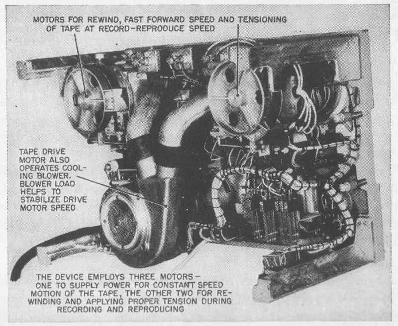
FIG. 6-36. Drive system for Magnetophone. ( Curtesy of U.S. Department of Commerce.)
page 163

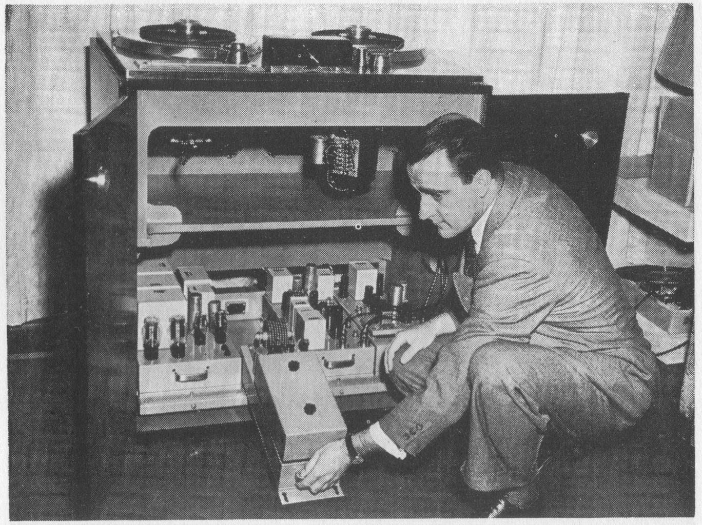
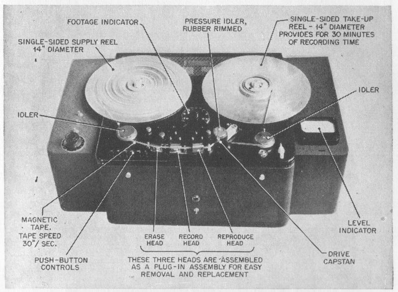
FIG. 6-37. The Rangertone. (Courtesy of Rangertone, Inc.)


-schreiber, was developed for use by the German armed forces. In this machine a capstan drive is employed, and its speed can be adjusted. The playing time for slowest speed is 70 mm. An unusual feature of the Tonschreiber consists in the use of a rotating playback head whereby recordings can be made at one tape speed and played back at a different tape speed without changing the pitch of a recorded signal.

Rangertone Tape Recorder

RANGERTONE. The Rangertone magnetic-tape recorder, shown in Fig. 6-37, is designed for broadcast and transcription purposes and is produced by Rangertone, Incorporated. Single-sided 14-inch-diameter reels are used, which, at a tape speed of 30 in. per sec., store a sufficient quantity of the medium topermit a continuous recording time of 1/2 hour. A plug-in head assembly sim-ilar to that of the German Magnetophone is employed. A calibrated elapsed-( ilne indicator is included, permitting exact reference to any portion of the recording. The different functions of the instrument are push-button-controlled. The electronic circuit of this instrument is shown in Fig. 6-38 and the fre(IIcncy response is shown in Fig. 6-39. Three motors are used, one each for the take-tip and supply reels and one for driving the constant-speed capstan. A standard VU meter indicates the recording level

page 164

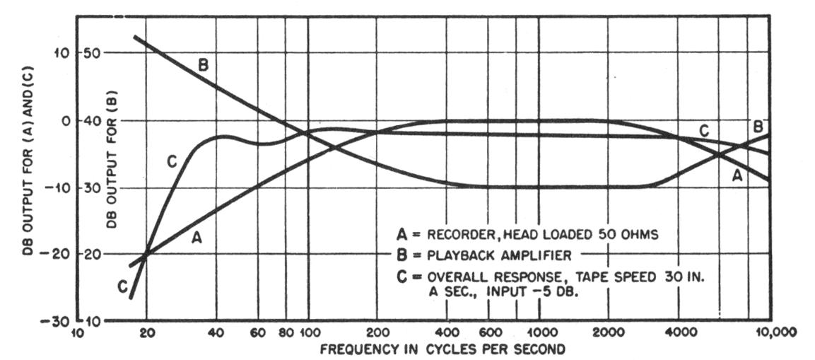
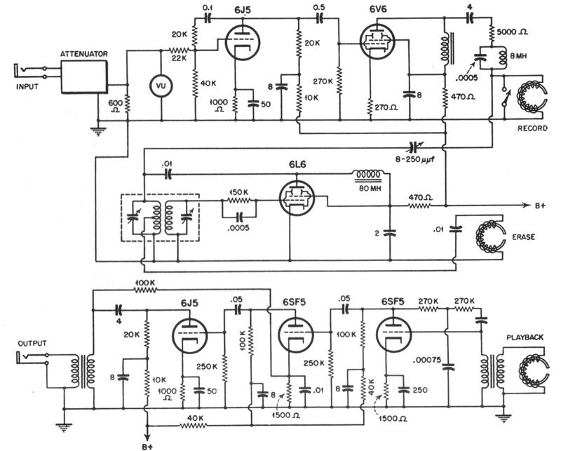
FIG. 6-38. Circuit diagram of Rangertone magnetic recorder. (From "Magnetic Tape Recorder for Movies and Radio," by R. H. Ranger, "Electronics," Oct.. 1947.)
FIG. 6-39. Frequency response of Rangertone magnetic recorder. (From "Magnetic Tape Recorder for Movies and Radio," by R. H. Ranger, "Electronics," Oct., 1947.)


Ampex Tape Recorder

AMPEX MAGNETIC TAPE RECORDER. The Ampex Magnetic Tape Recorder, the top of which is shown in Fig. 6-40, is manufactured by the Ampex Electric Corporation and is intended as studio equipment. It employs coated magnetic tape which moves at a speed of 30 in. per sec. during recording and reproducing. The rewind and fast forward speed is about 300 in. per sec. Each reel consists

page 165

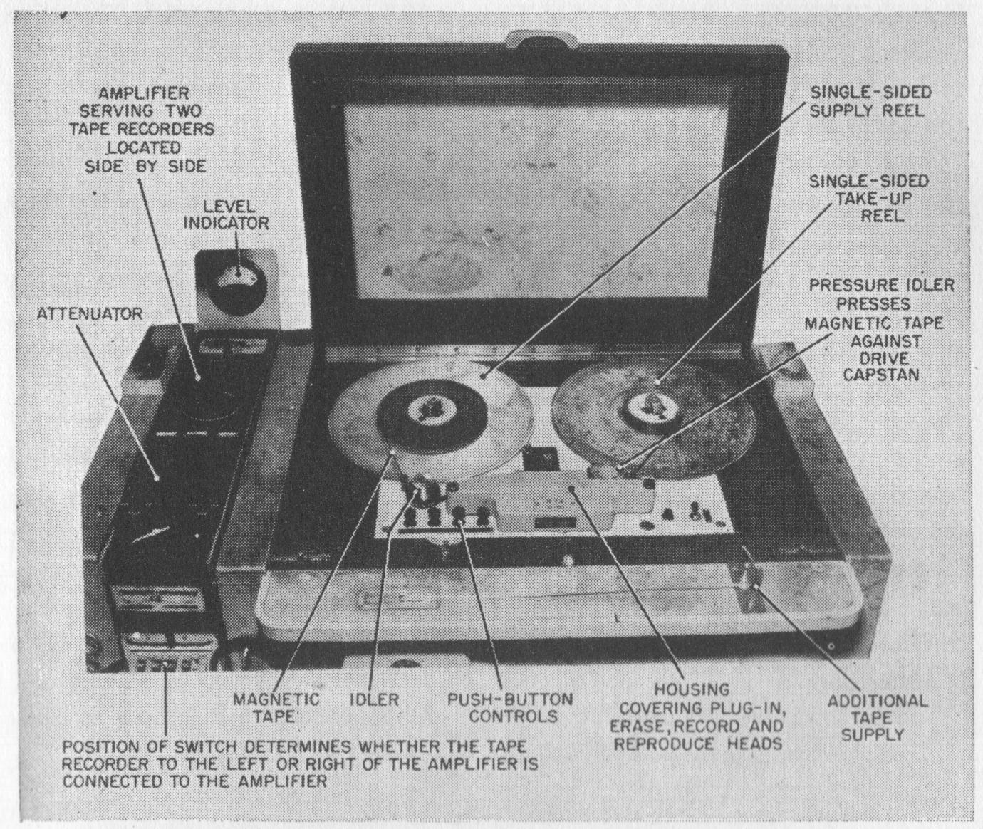
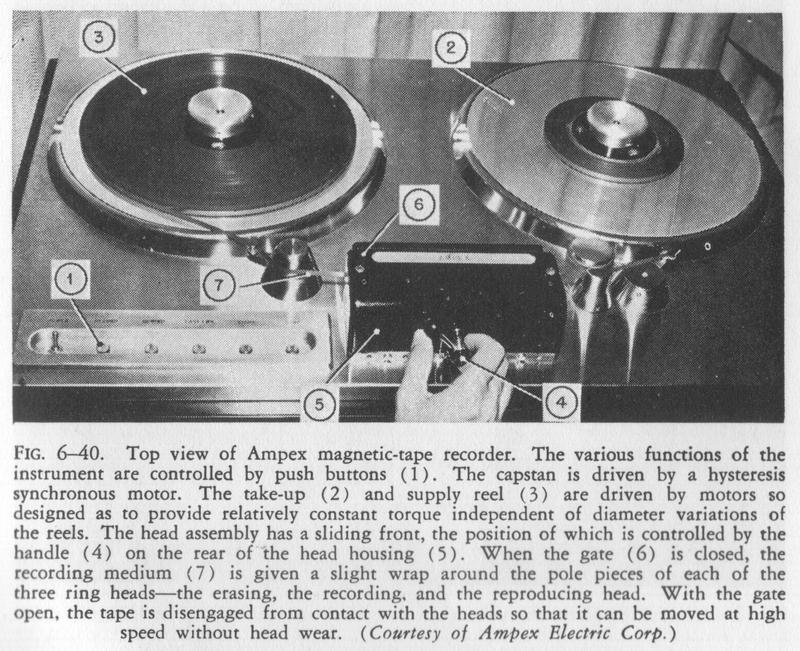
FIG. 6-40. Top view of Ampex magnetic-tape recorder. The various functions of the instrument are controlled by push buttons (1). The capstan is driven by a hysteresis synchronous motor. The take-up (2) and supply reel (3) are driven by motors so designed as to provide relatively constant torque independent of diameter variations of the reels. The head assembly has a sliding front, the position of which is controlled by the handle (4) on the rear of the head housing (5). When the gate (6) is closed, the recording medium (7) is given a slight wrap around the pole pieces of each of the three ring heads-the erasing, the recording, and the reproducing head. With the gate open, the tape is disengaged from contact with the heads so that it can be moved at high speed without head wear. (Courtesy of Ampex Electric Corp.)


of a 4-inch-diameter hub with a single 14-inch supporting disc and provides a recording time of 35 mm. Push buttons control slow forward, stop, rewind, and fast forward operations. It is reported that the over-all frequency is within ±1 db. from 30 to 15,000 c.ps. and that the total harmonic distortions do not exceed 1 per cent for any single frequency from 100 to 6,000 c_p.s. A signalto-noise ratio of better than 60 db. is claimed. Figure 6-41 shows the interior of the instrument.

Armour Tape Recorder

ARMOUR MAGNETIC-TAPE RECORDER. The Armour magnetic-tape recorder, shown in Fig. 6-42, is an experimental unit, employing coated tape that moves with a velocity of 8 in. per sec. It is designed for double-channel recording, one recording being made on the upper portion of the tape when the tape is moving in one direction, and the other recording being made on the lower portion of the tape when the tape moves in the reverse direction. A full hour's recording can be accommodated on a single 7-inch reel of tape. It is, of course, not possible to remove a section of tape for editing on one channel without removing the corresponding portion of the other channel.

Soundmirror BK-401 Tape Recorder

SOUNDMIRROR, MODEL BK-401. The Model BK-401 Soundmirror shown in Fig. 6 -43 is manufactured by The Brush Development Company and is de-

page 166

FIG. 6-41. Interior of the Ampex magnetic-tape recorder. For easy servicing, the different electronic sections are connected to each other and to the drive mechanism by means of plug connections. (Courtesy of Ampex Electric Corp.)
FIG. 6-42. Experimental Armour dual-channel tape recorder. (Courtesy of Armour Research Foundation.)
page 167

signed primarily for home-recording purposes. Recordings may be made either from a crystal microphone, supplied with the unit, or from a phonograph pickup or the detector stage of a radio. The recording medium is coated-paper tape, marketed under the name of Magnetic Ribbon. Tape is supplied in 7-inch reels, which contain a sufficient length for a continuous V2-hour recording. Difficulties with slit tilt are avoided in the Soundmirror by using the same head for both recording and playback; a separate head, spaced about 1 inch from the recording head, is employed for erasing. During recording or playback the medium is held against the recording and erasing heads by felt pressure pads, which are automatically withdrawn when the 'stop" switch is depressed. Any previous recording on the medium is automatically erased at the time a recording is made. Level is monitored during the recording period by means of a magic eye tube.

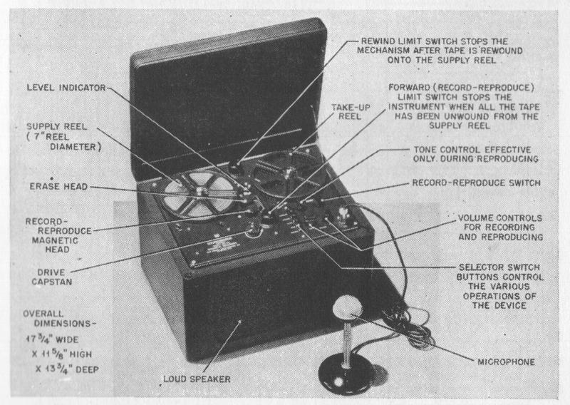
FIG. 6-43. BK-401 Soundmirror. (Courtesy of The Brush Development Company.)


The electronic portion of the Soundmirror, the circuit of which is shown in Fig. 6-44, provides sufficient equalization so that a frequency characteristic flit within ±3 db. from 100 to 5,000 c.p.s. is obtained. Separate amplifier channels are provided for recording and playback, the playback channel being available for use as a monitoring amplifier during recording, if so desired. As a consequence of the use of separate channels, independent control of gain in

page 168

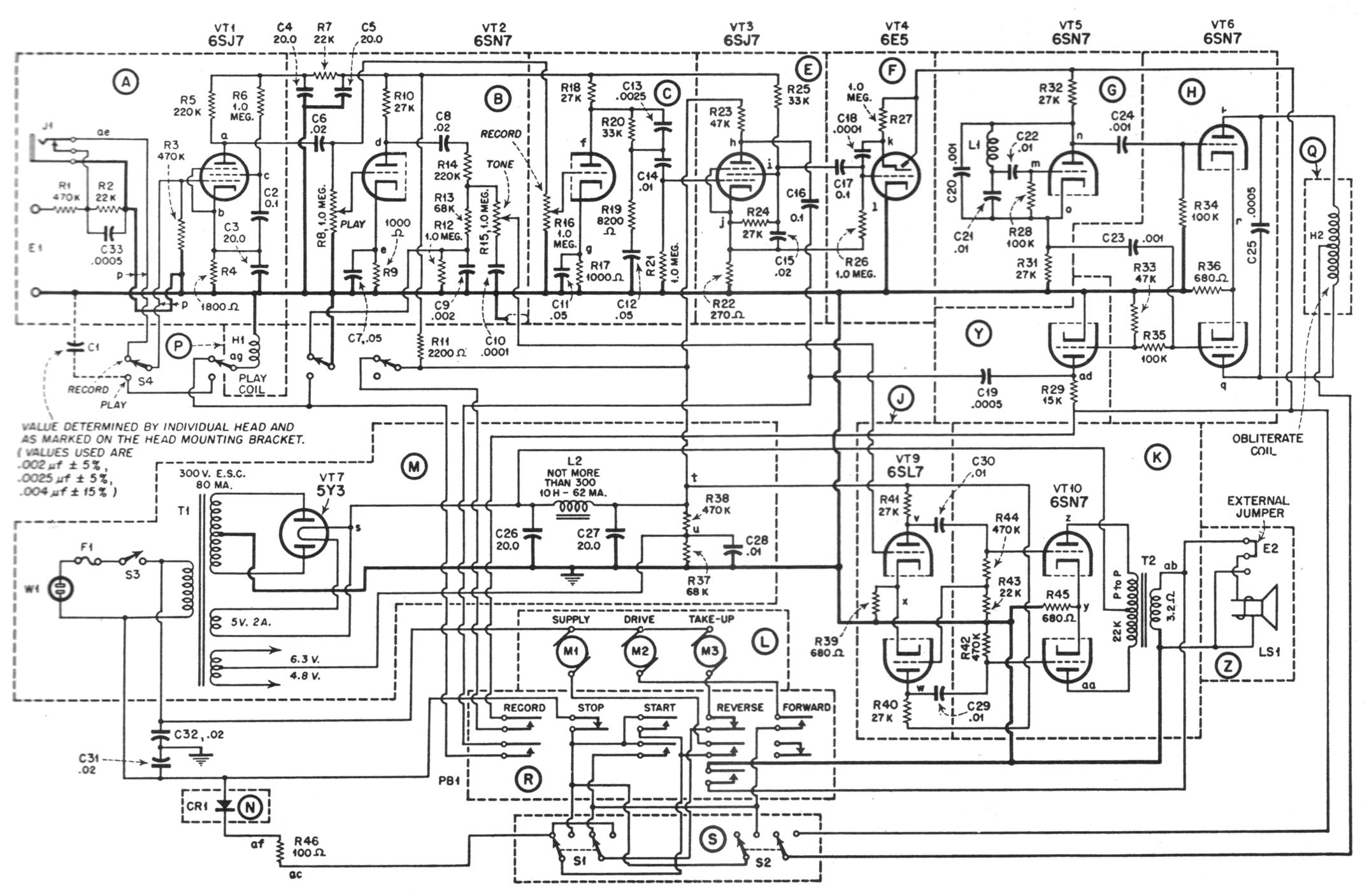
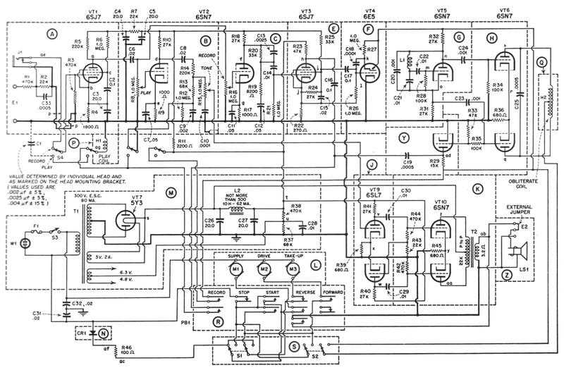
FIG. 6-44. Schematic diagram of BK-401 Soundmirror. In recording, the signal delivered from the microphone or radio is amplified in Secs. A, C, and E to produce the appropriate recording current in the magnetic head (identified as play coil). Biasing and erasing current is supplied from Secs. G, H, and Y. Level indication is obtained by use of the magic-eye tube in Sec. F. In reproduction, the signal supplied from the magnetic head is amplified in Secs. A and B. It passes through a phase inverter, Sec. J, to the pushpull output stage of Sec. K. Five push buttons, Sec. L, take care of the different functions of the device. Direct current from Sec. N is used to apply dynamic braking to supply and takeup motor for quickly bringing the reels to a stop after rewinding. (Courtesy of The Brush Development Company.)


page 169

recording and playback is possible. Some pre-emphasis of both high and low frequencies is provided during recording, the remainder of the equalization being obtained during playback. The tone control, which operates by attenuating high frequencies, affects only the playback portion of the circuit. Provision is made for guarding against accidentally throwing the functionselector switch into the erasing position when a recording is being played by requiring the operator to depress two switches simultaneously before a recording can be made. Separate gain controls are provided for recording and playback. The playback amplifier functions as a monitoring amplifier during recording, and its volume can be adjusted independently of the recording volume setting.

A more detailed description of the circuit elements of the Soundmirror is reviewed at this point, as an example of electronic design for magnetic recorders.

The input amplifier, Sec. A, uses the 6SJ7 tube (1) as a high-gain amplifier stage having a grid-to-plate gain in excess of 100 times. The microphone jack (J-1) disconnects the radio input circuit when the microphone plug is inserted. When recording, this stage amplifies the signal from microphorfe or radio input, and when playing back, it amplifies the signal from the reproducing head.

Half of the 6SN7 tube (2) in Sec. B is used as a second-stage amplifier and feeds the phase inverter (Sec. I). When recording, this stage serves as a monitor amplifier. When playing back, it amplifies the signal from the recording medium. This stage includes the play volume control and the frequency compensating circuits for playback.

The remaining triode of the 6SN7 tube (2) in Sec. C is the second-stage amplifier, which feeds Sec. E. This stage includes the record volume control, as well as the frequency compensating circuits, for use in the recording action.

Section E is the final stage used during recording and employs a 6SJ7 tube (3). During recording, it supplies the audio signal to the recording-reproducing head through the audio coupling capacitor. The 30-kc. bias current is introduced in this stage. It is impressed across the plate circuit of the 6SJ7 through a coupling capacitor and results in a current through the recording-head coil, which is a mixture (not a modulation) of the 30-kc. bias current and the audio frequency that is being recorded.

page 170

The 30-kc. potential across the recording head ranges from 40 to 60 volts.

A type 6E5 tube (4) as shown in Sec. F is used as the volume indicator when recording. It receives an audio voltage from the screen of the 6SJ7 second record-amplifier tube (3). The screen of the tube is used as the source for this indicating voltage so that the audio voltage present will be the only actuator of the volume indicator. Since the 30-kc. bias current is present in the plate circuit, the plate could not be used as a source of audio voltage alone for the indicator.

The first half of the 6SN7 (5) in Sec. G is used as the oscillator tube to generate the biasing and erasing frequency.

The two triodes of the type 6SN7 tube (6) in Sec. H are connected to form a push-pull amplifier, which receives its driving signal from Sec. G. During the recording operation, the plate-to-plate potential in this stage ranges between 80 and 100 volts and results in a 30-kc. current through the erase head coil of approximately 20 ma.

Section J shows a conventional phase-inverter stage and supplies the signal for the final amplifier stage. Section M indicates the power-supply arrangement.

There are, of course, many possible circuits for electronic amplifiers and associated equipments, but the same basic requirements fulfilled by the amplifier just described must be met in every case.

An outstanding feature of the Soundmirror is the exceptionally high rewind-record ratio, which is greater than 50 to 1. This ratio is achieved by means of a drive system using three motors, shown in Figs. 6-45 and 6-46. This arrangement makes it also possible to drive the tape at a high speed in the forward direction. High-speed motion in both directions is desirable to gain access to any desired position of a recording quickly. During the recording or playback period a constant-speed capstan drive is employed, which propels the medium by means of friction at 7.5 in. per sec. with less than 0.5 per cent peak-to-peak flutter or wow. The design of this capstan drive leans heavily on conventional phonograph turntable-drive mechanisms. The motor shaft is coupled through a free-floating rubber-tired idler to a flywheel that is part of the capstan (see Fig. 5-13). Tension is maintained on the tape during this period by means of separate motors attached to the shafts of each of the two reels. To obtain rapid rewind or rapid forward motion of the tape, it is removed from the capstan, and the motor attached to the reel on which the tape is to be wound is energized while the other motor is de-energized. By this means the tape can be completely wound from one reel to the other in about 40 sec.

Limit switches, actuated by light pressure from the medium, stop the motors when either reel is empty or in the event that the tape breaks while in motion. At the moment the limit switch is activated in rewinding, direct current, sup-

page 171

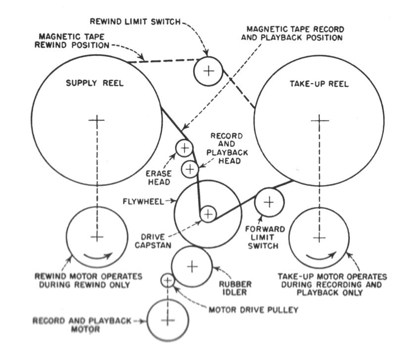
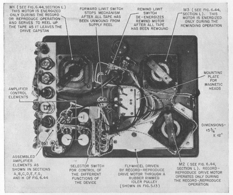
FIG. 6-45. Bottom view of top panel of the BK-401 Soundmirror. (Courtesy of The Brush Development Company.)
FIG. 6-46. Schematic diagram of the drive mechanism of the Brush Soundmirror, Model BK-401.
page 172

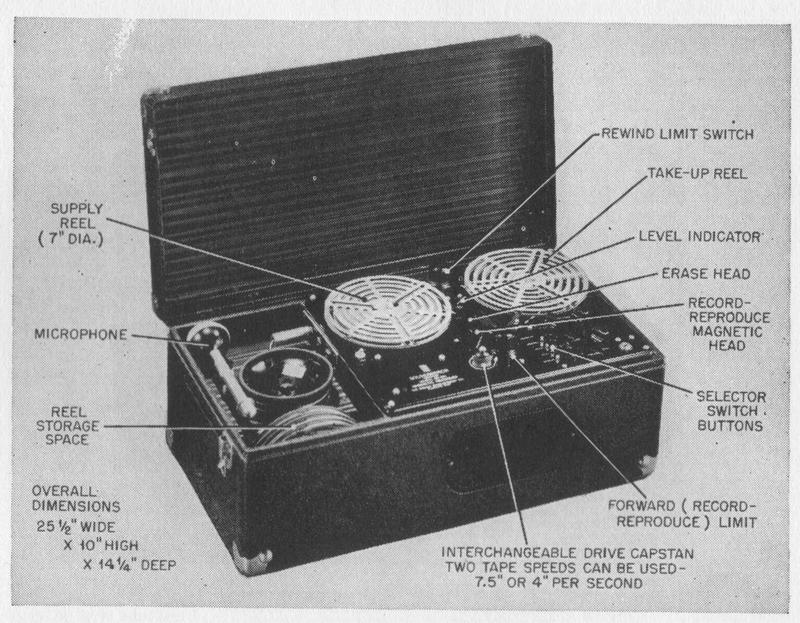
FIG. 6-47. Portable Soundinirror, Model BK-403. (Courtesy of The Brush Development Company.)


-plied by a selenium rectifier, as shown in Sec. N of the circuit diagram, is applied to the field coils of the motor attached to the reel from which tape is being drawn. This direct current applies magnetic braking to the rotor of this motor and prevents the tape from being thrown from the reel.

A portable model of the Soundmirror, the BK-403, is manufactured for use by broadcast stations, recording studios, police officers, and others who require equipment for making on-the-spot recordings. It is substantially identical with the Model BK-401, except that two separate, removable capstans are provided to enable recordings to be made either at the speed of 7.5 in. per sec., or at a speed of 4 in. per sec. The latter speed is used when only voice frequencies are to be recorded and permits continuous recordings of about 1 hour. For greater flexibility in meeting standard communication impedance requirements, 500ohm input and output are provided. The unit, shown in Fig. 6-47, is housed in a suitcase which is equipped with storage compartments for the microphone and reels of tape.

Soundmirror BK-411 Tape Recorder

SOUNDMIRROR, MODEL BK-411. The model BK-411 Soundmirror shown in Fig. 6-48 is manufactured by The Brush Development Company and is, like the BK-401 Soundmirror, primarily intended for home recording. Particular

page 173

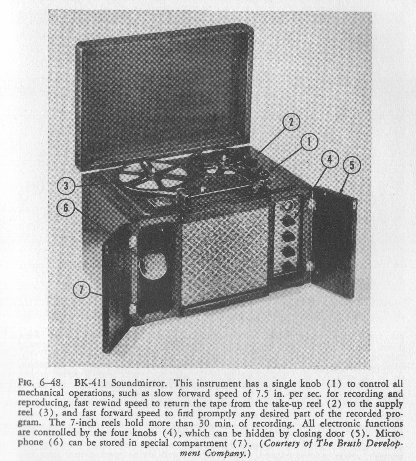
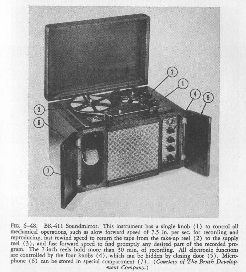
FIG. 6-48. BK-411 Soundmirror. This instrument has a single knob (1) to control all mechanical operations, such as slow forward speed of 7.5 in. per sec. for recording and reproducing, fast rewind speed to return the tape from the take-up reel (2) to the supply reel (3), and fast forward speed to find promptly any desired part of the recorded program. The 7-inch reels hold more than 30 mm. of recording. All electronic functions are controlled by the four knobs (4), which can be hidden by closing door (5). Microphone (6) can be stored in special compartment (7). (Courtesy of The Brush Development Company.)


emphasis has been laid in its design upon simplicity of operation. It is probably the first commercial magnetic recorder that stops when only a few turns of tape are left on the supply reel and then automatically rewinds the tape. In Fig. 6-49 the top view and in Fig. 6-SO the underneath view of the drive mechanism are shown.

A single lever controls all the mechanical operations of the drive mechanism, such as the slow forward speed of 7.5 in. per sec. for recording and playback and the fast forward and rewind speed, which is about ten times faster. Alternatingcurrent biasing is employed. Fcr erasing, a permanent-magnet structure is used, which is similar to that shown in Fig 5-2. The permanent-magnet

page 174

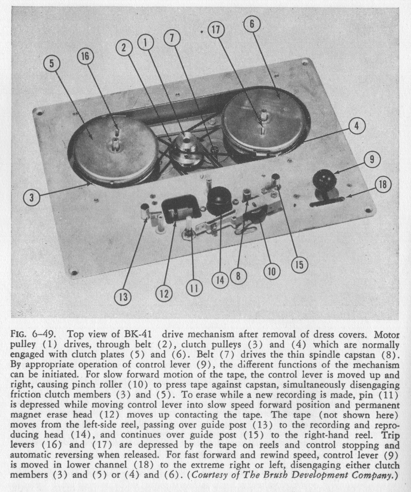
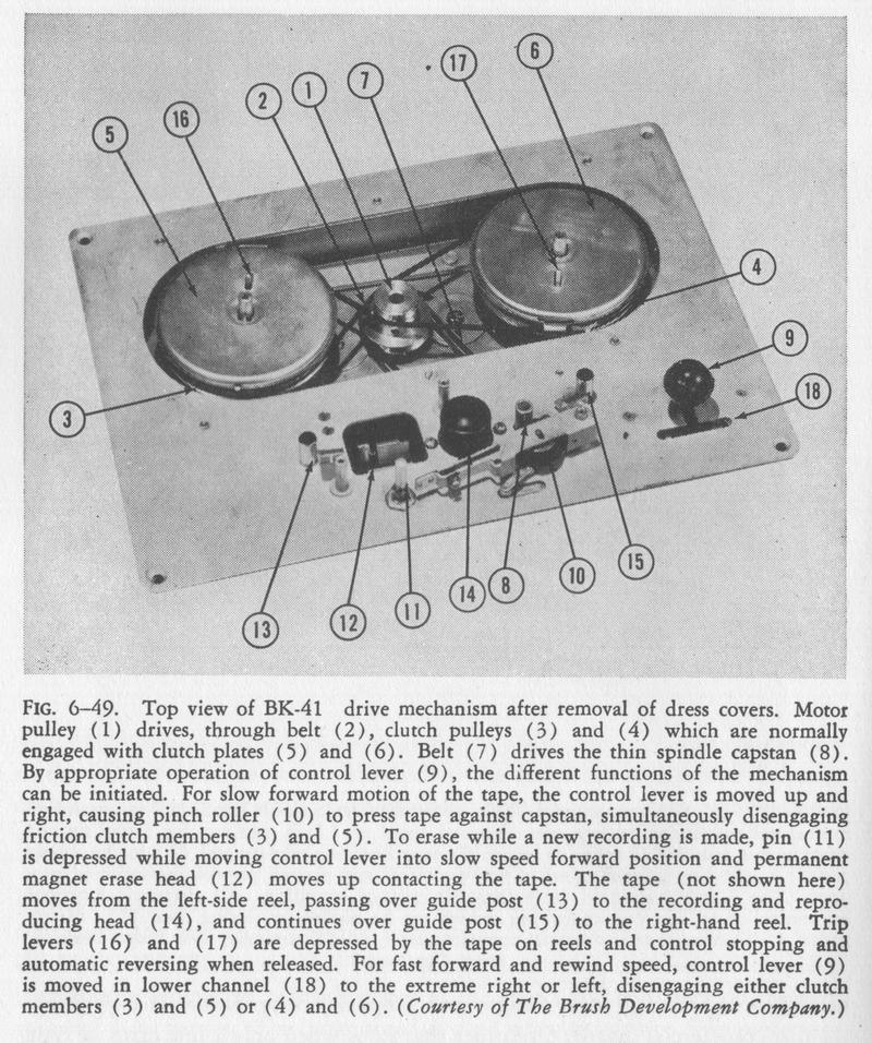
FIG. 6-49. Top view of BK-41 drive mechanism after removal of dress covers. Motor pulley (1) drives, through belt (2), clutch pulleys (3) and (4) which are normally engaged with clutch plates (5) and (6). Belt (7) drives the thin spindle capstan (8). By appropriate operation of control lever (9), the different functions of the mechanism can be initiated. For slow forward motion of the tape, the control lever is moved up and right, causing pinch roller (10) to press tape against capstan, simultaneously disengaging friction clutch members (3) and (5). To erase while a new recording is made, pin (11) is depressed while moving control lever into slow speed forward position and permanent magnet erase head (12) moves up contacting the tape. The tape (not shown here) moves from the left-side reel, passing over guide post (13) to the recording and reproducing head (14), and continues over guide post (15) to the right-hand reel. Trip levers (16) and (17) are depressed by the tape on reels and control stopping and automatic reversing when released. For fast forward and rewind speed, control lever (9) is moved in lower channel (18) to the extreme right or left, disengaging either clutch members (3) and (5) or (4) and (6). (Courtesy of The Brush Development Company.)


erasing head is mounted on a hinged platform, which is raised and brought into contact with the tape by pressing the erasing button while moving the control lever into the slow-speed-forward position. The erasing head is then held close to the tape by a self-locking lever linkage until the instrument is stopped or until the mechanism is tripped to rewind automatically.

An interesting feature of this equipment is the 3/32-inch spindle which acts as a capstan as soon as a rubber-tired pinch roller sandwiches the tape against it. Because of the high speed with which this spindle rotates, only a small fly-

page 175

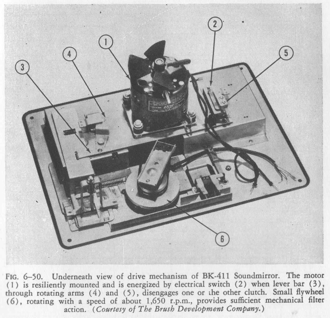
FIG. 6-50. Underneath view of drive mechanism of BK-411 Soundmirror. The motor (1) is resiliently mounted and is energized by electrical switch (2) when lever bar (3), through rotating arms (4) and (5), disengages one or the other clutch. Small flywheel (6), rotating with a speed of about 1,650 r.p.m., provides sufficient mechanical filter action. (Courtesy of The Brush Development Company.)


wheel is necessary to minimize variations in the tape motion. A single motor drives, through one rubber belt, two friction clutches and, through another rubber belt, the small-diameter drive shaft. These friction clutches are normally engaged and tend to drive the tape reels in opposite directions. Depending upon the desired direction of the tape motion, one or the other friction clutch is disengaged. Built into the supporting tables for the tape reels, which are part of these friction clutches, are little levers that are depressed as long as there is sufficient tape on the reel. When these levers are released after almost complete removal of the tape from the reels, they operate the trip mechanism, which causes, after recording and playback, automatic rewinding and, after the tape is rewound, automatic stopping of the device. The same head is used for recording and reproduction. The head can he rotated through a small arc so that a position of minimum hum pickup can be found.

Figure 6 -51 shows the circuit diagram as used in this device.

page 176

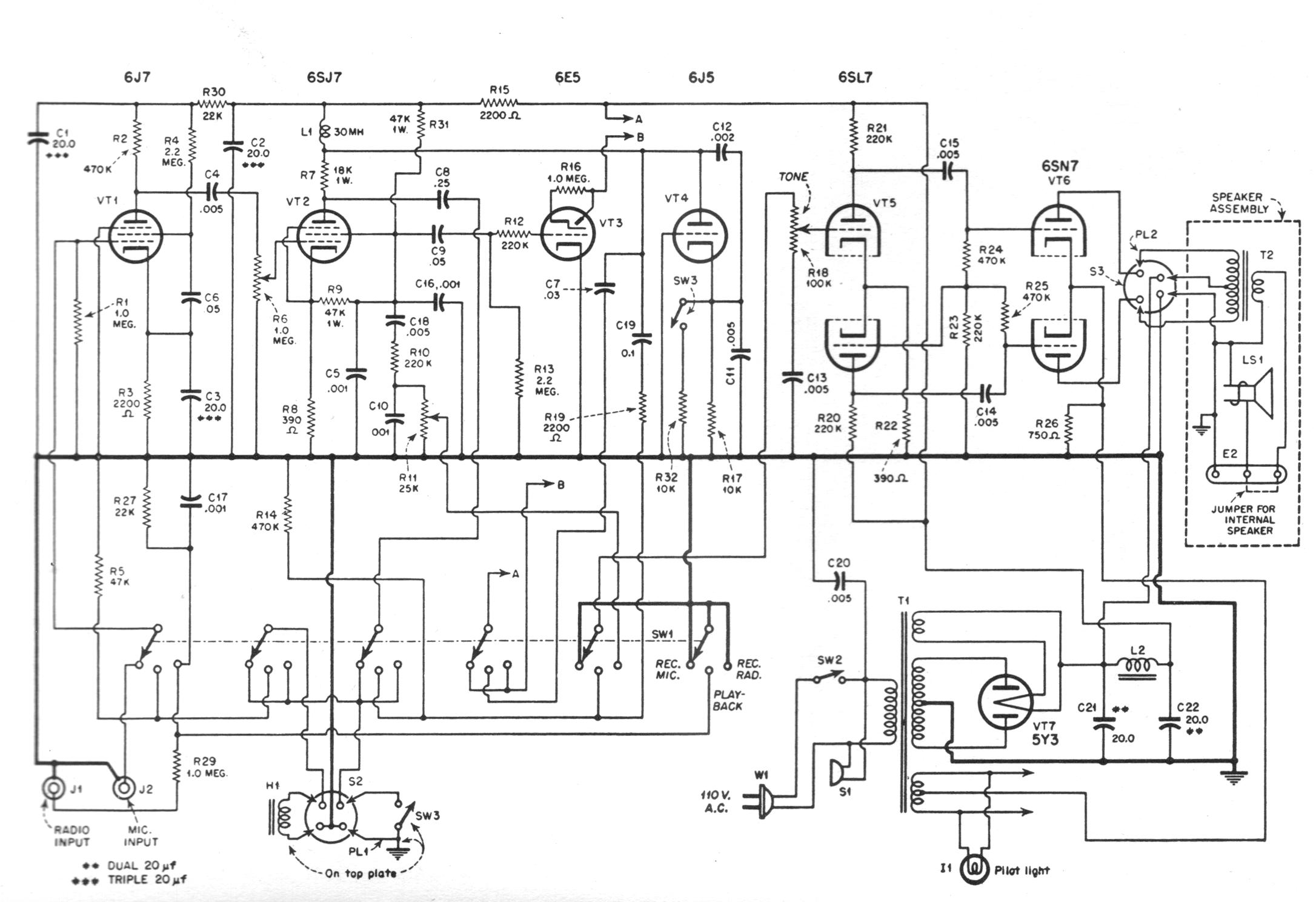
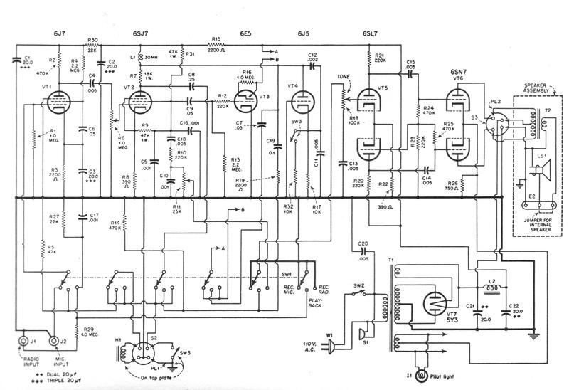
FIG. 6-51. Tube VT1 acts as a voltage-gain stage and is connected either to the microphone or radio for recording or to the magnetic head for reproduction. When recording, VT2 produces a constant recording current for a given voltage input. The screen of VT2 functioning like a plate of a low-gain triode serves as a source for the level indicator rube VT3 and feeds the phase inverter VT5, and thus the push-pull output stage VT6, to secure .1 monitor signal when recording from the radio receiver. Alternating-current bias is supplied from RT4 and is superimposed on the signal. In reproduction, VT5 is coupled to the plate of VT2 to obtain higher gain. L1, which controls the bias frequency in recording, boosts the high requencies in playback. Low frequency compensation in playback results from the loading of R19 and C19 upon the stage VT2.
page 177

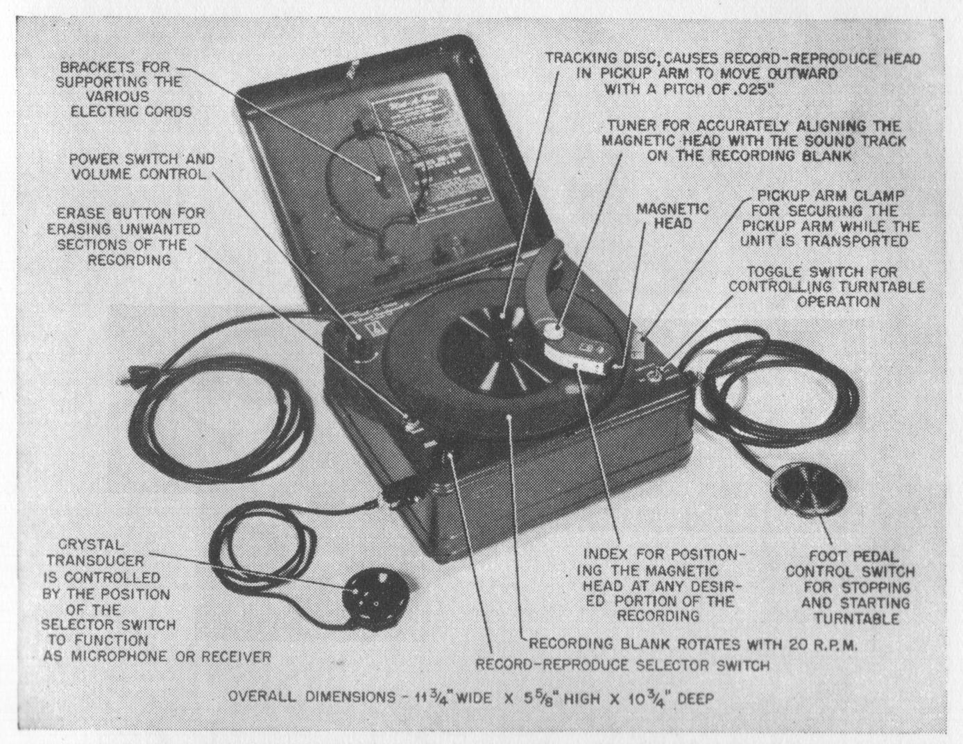
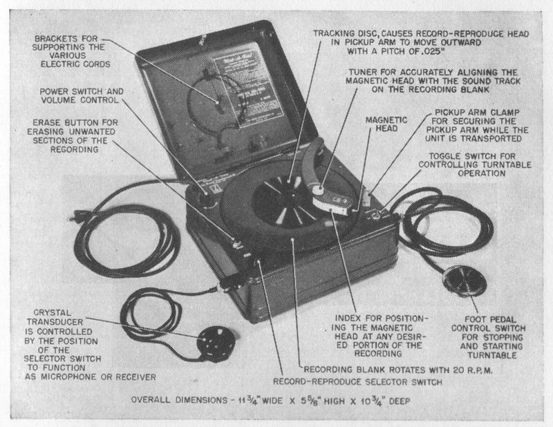
FIG. 6-52. BK-503 Mail-A-Voice. (Courtesy of The Brush Development Company.)


COATED-DISC RECORDERS

Mail-A-Voice Disc Recorder

MAIL-A-VOICE. The model BK-503 Mail-A-Voice (Fig. 6-52), manufactured by The Brush Development Company, represents an entirely different approach to the problem of storing information on a magnetic medium. The recording material in this case is in the form of a 9-inch disc, and the sound track is a spiral running from an inner diameter of 5 inches to the outer edge. The recording track has a width of 0.014 inch, and the pitch of the spiral is 0.025 inch. Despite this close spacing, no noticeable crosstalk can be detected. The powder-coated paper discs can be folded and mailed like an ordinary letter. No guide grooves are provided on the coated discs. The recording-playback head

page 178

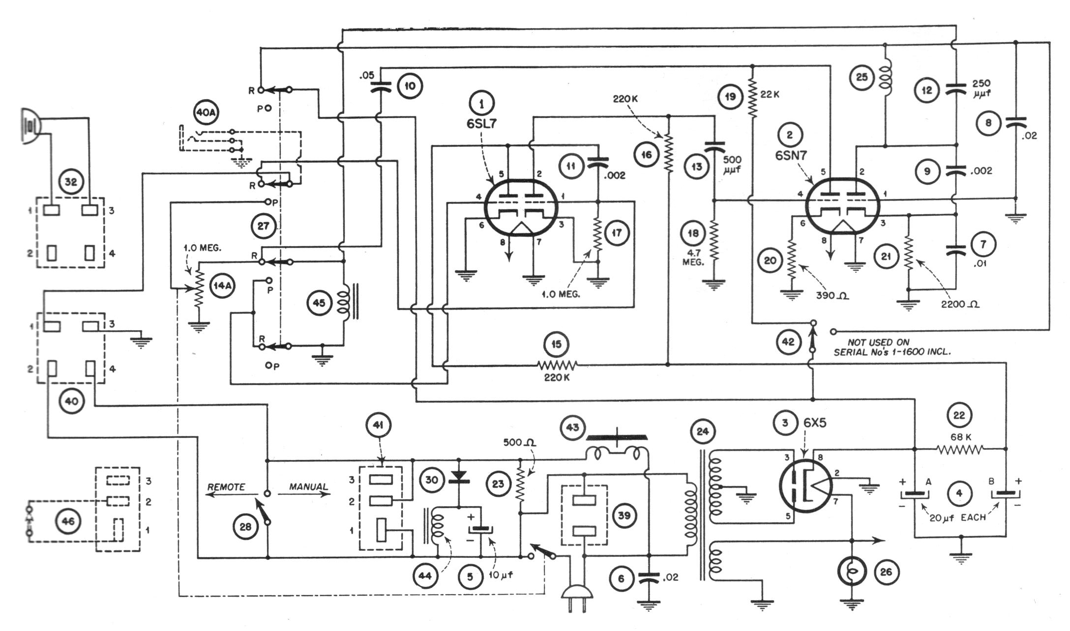
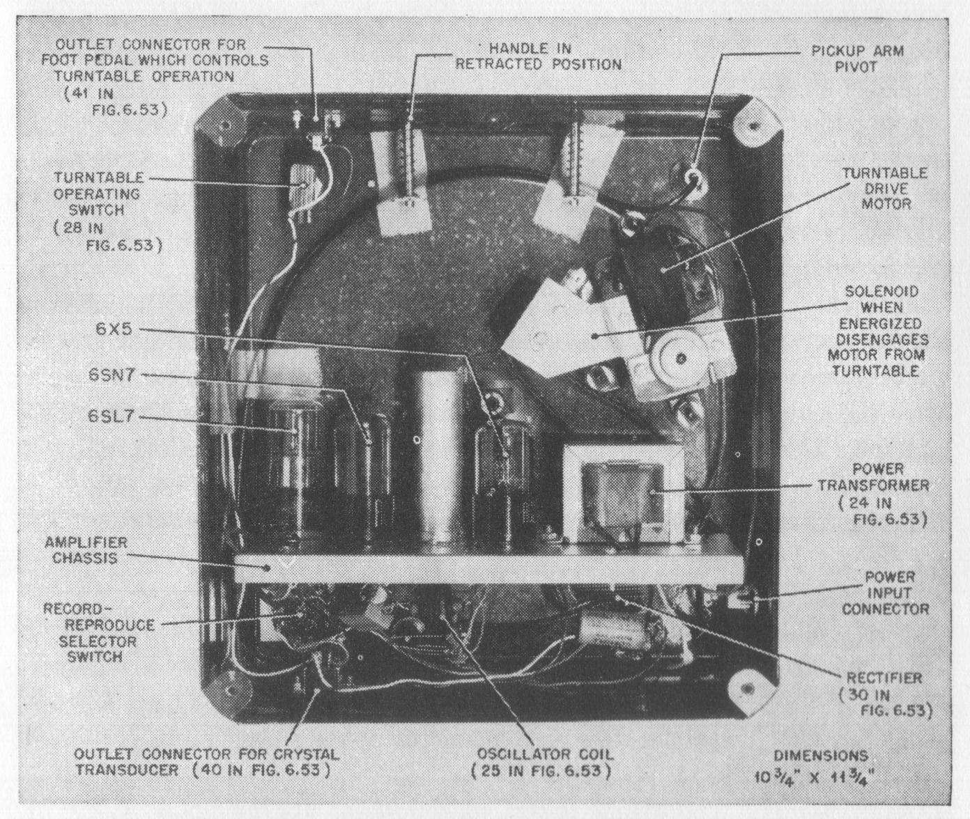
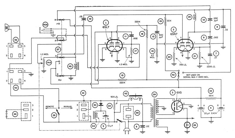
FIG. 6-53. Circuit diagram of BK-503 Mail-A-Voice. In recording, the second half of the 6SL7 tube and the first half of the 6SN7 tube are used to amplify the signal delivered from the crystal transducer so that sufficient recording current for full modulation is supplied to head (45). The second half of the 6SN7 tube generates the biasing current. In reproduction, the head (45) is connected to the first half of the 6SL7 tube, since more gain is reçuired than in recording. The crystal transducer receives the signal from the plate of the first section of the 6SN7 tube. The oscillator section is de-energized. Stop and start are controlled by the foot pedal (46), which in operating condition short circuits solenoid (44). The energized solenoid decouples the motor from the turntable. (Courtesy of The Brush Development Company.)
page 179

FIG. 6-54. Bottom view of BK-503 Mail-A-Voice. (Courtesy of The Brush Development Company.)


is guided on a spiral path along the disc by a stylus located on the tone arm, which tracks the guide disc. The amplifier, the circuit of which is shown in Fig. 6-53, covers the voice frequency range only. With a minimum of tubes (two double triodes), all the necessary functions are performed. No level indicator is employed. Even with close and loud talking into the microphone, the distortions are not sufficient to impair intelligibility. Alternating-current biasing is used in making recordings,

page 180

but erasing is effected by d-c saturation of the medium by means of a permanent magnet. A previous recording is erased by holding this magnet on the disc while the turntable revolves several times. The turntable rotates 20 r.p.m., resulting in a total recording time of slightly over 3 mm. This instrument deserves special mention because it presently represents the most simple and basically the most inexpensive mechanical 'rid electrical design for a magnetic recorder that has been produced commercially. A single crystal headphone is used both as a recording microphone and as a playback earphone.

The model BK-503 Mail-A-Voice shown in the illustration is intended primarily for dictation purposes. A solenoid, shown in the underneath view of the instrument in Fig. 6-54, retracts the driving idler from the turntable rim when the "stop" switch is opened and simultaneously applies a brake to the turntable. This stops the turntable so quickly that practically no time is lost in 'coasting." Another model of the Mail-A-Voice, the BK-501, not shown, is intended primarily for correspondence and dispenses with the solenoid.

BIBLIOGRAPHY

Periodicals

MALLINA, R. F., "Mirror for Voice," Bell Labs. Record, Vol. 13 (March., 1935), pp. 200-202.

VOLK, T., "A.E.G. Magnetophone," A.E.G. Mitt., No. 9 (Sept., 1935), pp.229-3Ol.

VOLK, T., "Magnetophone-A New Sound Recording Apparatus," Filmtech. Vol. 11 (Oct., 1935), pp. 229-231.

HANSEN, W. H., "The Magnetophon," Elektrotech., Vol. 56 (Nov. 7, 1935), p. 1232.

HAMILTON, H. E., "The Blattnerphone-Its Operation and Use," Elec. Digest,Dec., 1935, p. 347.

"New Steel Tone Tape Machine," Elec. Comm., Vol. 15 (July, 1936), pp. 62-69.

BEGUN, S. J., "Magnetic Recording-Reproducing Machine for Objective Speech Study," J. Soc. Motion Picture Engrs., Vol. 29 (Nov. 2, 1937), pp. 216-218.

SCHULLER, E., "Magnetophone," Ver. Dent. Elek. Fachberichte, 1936, pp. 175-177.

MALLOY, T. J., "Magnetic Recorder," Electronics, Vol. Ii (Jan., 1938), pp.30-32.

BEGUN, S. J., "Magnetic Recording," Electronics, Vol. 11 (Sept., 1938), pp.30-32.

BEGUN, S. J., "A New Magnetic Recorder and Its Adaptations," J. Soc. Motion Picture Engrs., Vol. 33 (Nov., 1939), pp. 538-547.

"The Mirrophone," Wireless World, Vol. 48 (Feb., 1942), pp. 42-43.

WILDBOLZ, H., "Das Textophon," Schweizer Archly, Vol. 9 (Oct., 1942, Sup.)pp. 9-12.

"Wire Recorders for Army," Electronics, Vol. 16 (Oct., 1943), pp. 231, 236.

CAMRAS, M., "A New Magnetic Wire Recorder." Radio News, Radionics Sec., Vol 30 (Nov., 1943), pp. 3-5, 38-39.

page 181


"Voice Recorded on Hair-Like Wire," Gen. Elec. Rev., Vol. 46 (Dec., 1943), p. 694.

PUGSLEY, D. W., "Engineering Details of Magnetic Wire Recorder," Electronic Indus., Vol. 3 (Jan., 1944), pp. 116-118, 206, 210, 212.

OPPERMAN, R. H., "Record Voice on Hair-Like Wire," J. Franklin Inst., Vol.237 (Feb., 1944), p. 160.

'Portable Sound Recording Devices," Electronics, Vol. 17 (Apr., 1944), p 302.

SELBY, M. C., "Investigation of Magnetic Tape Recorders," Electronics, Vol. 17 (May, 1944), pp. 133-135, 302.

"B.B.C. Mobile Recording Equipment," Wireless World, Vol. 50 (May, 1944), pp. 133-135.

"Magnetic Wire Recorder," Electronics, Vol. 18 (Feb., 1945), p. 386.

"Pocket Model Wire Recorder Designed," Electronic Indus., Vol. 4 (May, 1945), p. 254.

"German's Tape Recorder, Magnetophon, Is Termed Superior to Other Methods," Broadcasting, (Sept. 3, 1945), p. 24.

"German Magnetic-Tape Recorder," Electronics, Vol. 18 (Nov., 1945), pp. 402, 403.

"German Tape-Recording Equipment," Electronic Eng., Vol. 18 (Feb., 1946), p. 54.

POWER, R. A., "The German Magnetophon," Wireless World, Vol. 52 (June, 1946), pp. 195-198.

JAVITZ, A. E., "An Appraisal of Design Trends in Magnetic Sound Recorders," Elec. Mfg., Vol. 37 (June, 1946), pp. 107-111, 228, 230, 232, 234, 236, 238, 240, 242, 244.

BEGUN, S. J., "Recent Developments in the Field of Magnetic Recording," J. Soc. Motion Picture Engrs., Vol. 48, No. 1 (Jan., 1947), pp. 1-13.

TINKHAM, R. J., and J. S. BoYms, "A Magnetic Sound Recording of Advanced Design," J. Soc. Motion Picture Engrs., Vol. 48 (Jan., 1947), pp. 29-35.

"Paper Tape Magnetic Recorder," Tele-Tech, Vol. 6 (Jan., 1947), pp. 88, 89.

CHASE, H., "Designing Wire Recorder Unit for Low-Cost Quantity Production," Elec. Mfg., Vol. 39 (Jan., 1947), pp. 122-125, 172, 174, 176.

"Pocket Magnetic Recorder," Tele-Tech, Vol. 6 (Apr., 1947), p. 29.

Magnetophon Recorders," Wireless World, Vol. 53 (Apr. 1947), p. 128.

JAMES, J. H., "Magnetic Playback-Recorder Using Paper Discs," Communications, Vol. 27 (Apr., 1947), pp. 32, 55-58.

O'BRIEN, R. S., "Adapting Paper Tape Recorders for Broadcasting," Audio Eng., Vol. 31 (June, 1947), pp. 10-14, 48.

RANGER, R. H., "Magnetic Tape Recorder for Movies and Radio," Electronics, Vol. 20 (Oct., 1947), pp. 99-103.

DRENNER, DON V. R., "The Magnetophone," Audio Eng., Vol. 31 (Oct., 1947), pp 7-11, 35.

Sources:


© 2002 by Steven E. Schoenherr. All rights reserved.

Recording Technology History| this page revised 10/30/02 by Schoenherr